


Return to Section TOC Return to Section TOC Return to Section TOC Return to Section TOC
Return to Master TOC Return to Master TOC Return to Master TOC Return to Master TOC
THEORY OF OPERATION
E-6 E-6
POWER WAVE 450
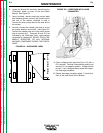
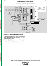
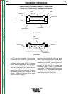
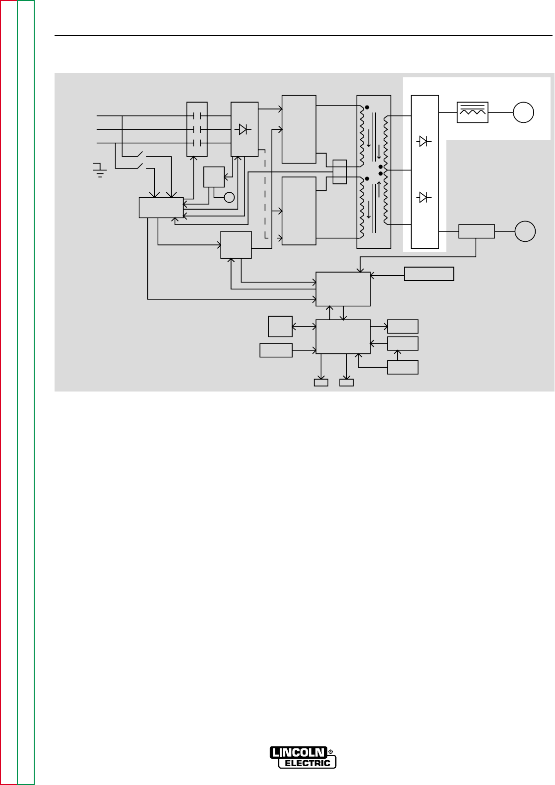
OUTPUT RECTIFIER AND CHOKE
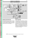
The Output Rectifier receives the AC output from the
Main Transformer secondary and rectifies it to a DC
level with a 40 kHz ripple.
Since the Output Choke is in series with the positive
leg of the Output Rectifier and also in series with the
welding load, a filtered DC output is applied to the
machine output terminals.
FIGURE E.6 – OUTPUT RECTIFIER AND CHOKE
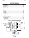
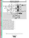
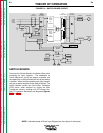
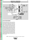
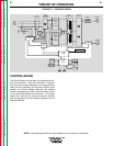
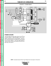
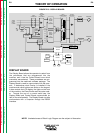
NOTE: Unshaded areas of Block Logic Diagram are the subject of discussion.
CONTROL
BOARD
DISPLAY
BOARD
PROTECTION
BOARD
AUX.
TRANS
POWER
BOARD
CT
CONTACTOR
INPUT
INPUT
RECTIFIER
AND
RECONNECT
SWITCH
BOARD
FET
ASSEMBLY
SWITCH
BOARD
FET
ASSEMBLY
MAIN
TRAMSFORMER
OUTPUT
RECTIFIER
SHUNT
CHOKE POSITIVE
NEGATIVE
SNUBBER AND
LEADS
SENSE
LCD
DISPLAY
KEYPAD
OVERLAY
WATER
COOLER
PC
INTERFACE
INPUT
LINE
SWITCH
FAN
WF1 WF2
THREE
PHASE
INPUT
POWER
LEFT
RIGHT