


F-82 F-82
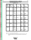
RECONNECT SWITCH TEST 1
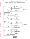
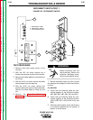
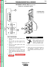
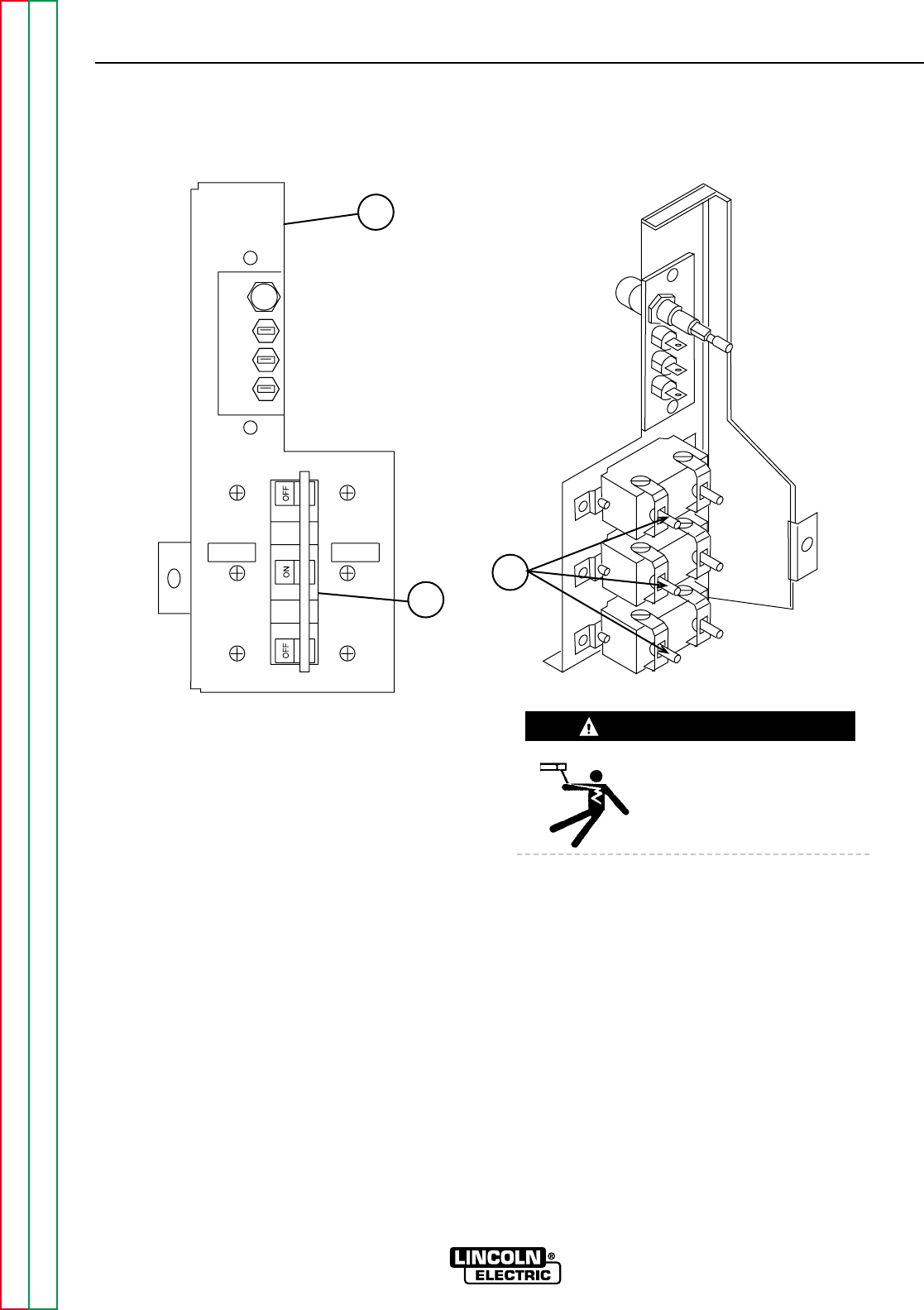
FIGURE F.26 - RECONNECT SWITCH
1
2
3
TROUBLESHOOTING & REPAIR
TEST PROCEDURE
1. Remove main input supply power to the
machine.
2. With the 3/8" nut driver, remove the 4
screws that hold the handle to the machine.
3. Remove the rubber gasket (cover seal) from
the lift bail.
4. With the 5/16" nut driver, remove the sheet
metal screws from the case top.
5. With the 5/16" nut driver, remove the
screws holding the right and left case sides.
Remove the case sides by lifting up and
out.
6. Perform the Capacitor Discharge
Procedure described earlier in this section
of the manual.
Before continuing with the
test procedure, perform the
capacitor discharge proce-
dure to avoid electric shock.
7. Test the reconnect switch for short circuits
according to the voltage for which the machine
is wired:
For 230 VAC:
A. Check that the following leads are con-
nected together at the reconnect switch:
#9A, #9B, #9C, #9D, #9K, #9J, and POS.
B. Check that the following leads are con-
nected together at the reconnect switch:
#12A, #12B, #12C, #12D, #12K, #12J, and
NEG.
C. With the volt/ohmmeter, check that there is
no continuity between the two groups of
leads in A and B above.
POWER WAVE 450
Return to Section TOC Return to Section TOC Return to Section TOC Return to Section TOC
Return to Master TOC Return to Master TOC Return to Master TOC Return to Master TOC
WARNING
1. RECONNECT PANEL
2. RECONNECT SWITCH
3. LEAD CONNECTIONS