


Return to Section TOC Return to Section TOC Return to Section TOC Return to Section TOC
Return to Master TOC Return to Master TOC Return to Master TOC Return to Master TOC
F-194 F-194
TROUBLESHOOTING & REPAIR
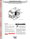
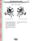
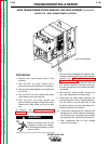
21. Remove the water cooler assembly in
order to access the retainer clips that hold
the bottom of the FET module assembly in
place. (Complete removal of the unit
should not be necessary.) Refer to the
Water Cooler Removal and
Replacement Procedure in this section
of the module.
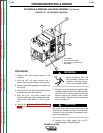
22. Remove the locking bar from the top of
the subframe where it secures the FET
module assembly. Depress the top and
bottom retainer clips with the slot head
screw driver so that the FET module
assembly can slide forward.
23. Slowly lift and remove the subframe, mak-
ing sure no clips, cable ties, or lead con-
nections are still holding it.
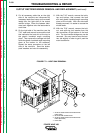
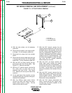
24. With the wire cutters, cut all necessary
cable ties holding the FET module assem-
bly to the wiring harness. Using needle
nose pliers, disconnect the leads attached
to the FET module assembly (all red and
white leads should remain connected).
Refer to the Wiring Diagram to determine
which leads should be disconnected. The
main transformer and the reconnect mod-
ule must be free of the FET module
assembly. Also disconnect the thermostat
lead.
25. Carefully lift the FET module assembly
and remove it from the machine.
26. With the FET module assembly removed,
the main transformer, background choke,
and output choke are now easily accessi-
ble. Refer to the Main Transformer
Removal and Replacement Procedure
in this section of the module.
Replacement of the FET Module Assembly:
27. Carefully set the assembly into the bottom
of the machine. The terminal label should
face the front (toward the main trans-
former).
28. Connect all leads to their appropriate ter-
minals on the assembly. Use the Wiring
Diagram for reference.
29. Carefully position the subframe on top of
the FET module assembly. Slide the
assembly into place so that the retainer
clips snap into their slots, top and bottom.
Fit the locking bar into place on top of the
subframe to secure the FET module
assembly.
POWER WAVE 450
FET MODULE REMOVAL AND REPLACEMENT (continued)