


F-26 F-26
CAPACITOR DISCHARGE PROCEDURE (continued)
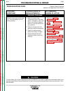
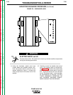
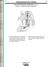
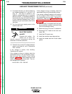
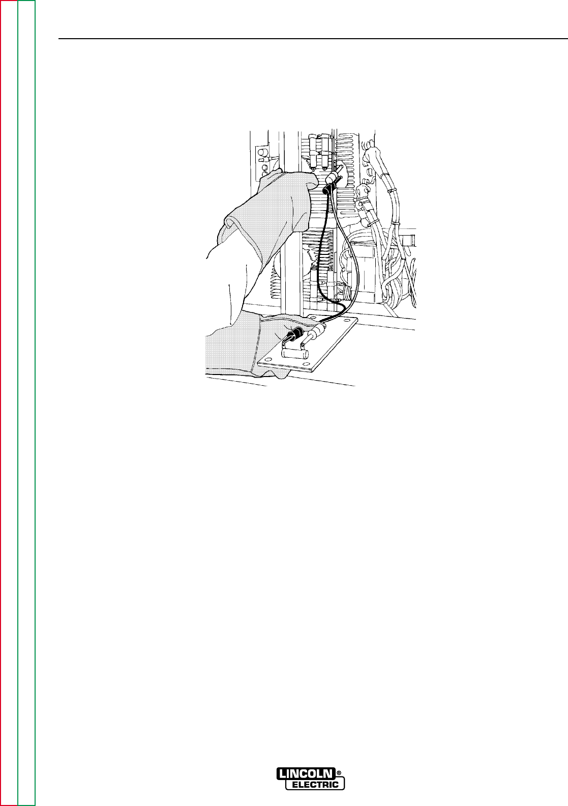
FIGURE F.4 - RESISTOR WITH LEADS CONNECTED.
TROUBLESHOOTING & REPAIR
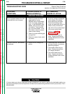
11. Check the voltage across terminals #9 and
#12 with the DC voltmeter. Terminal #9
has positive polarity and terminal #12 has
negative polarity. Voltage should be zero.
If any voltage remains, repeat this capaci-
tor discharge procedure.
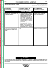
12. Repeat discharge procedure steps 9, 10,
and 11 for each of the other three switch
boards of the FET or IGBT switch board
assembly.
POWER WAVE 450
Return to Section TOC Return to Section TOC Return to Section TOC Return to Section TOC
Return to Master TOC Return to Master TOC Return to Master TOC Return to Master TOC