


F-177 F-177
PRINTED CIRCUIT BOARD REMOVAL AND REPLACEMENT
(CONTROL BOARD, POWER BOARD, AND PROTECTION BOARD) (continued)
TROUBLESHOOTING & REPAIR
Be sure to follow the recommended static-free
methods for handling printed circuit boards.
Failure to do so can result in permanent dam-
age to the equipment.
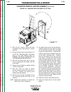
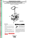
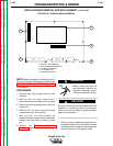
8. Remove the molex plugs from the PC board
you are removing.
NOTE: The plugs are numbered in order from
left to right.
9. Depress the two PC board retainer clips
located on the left and right sides of the
board. Lift the board by the clips to remove
it.
10. When reinstalling the PC board, make cer-
tain the tabs at the bottom of the board fit
into the slots on the compartment floor.
When the board is properly seated, the
retainer clips will snap into the locked
position.
11. Install the molex plugs removed earlier.
Be sure to fit the each plug into its respec-
tive receptacle on the board.
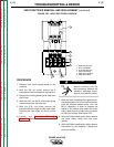
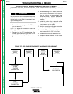
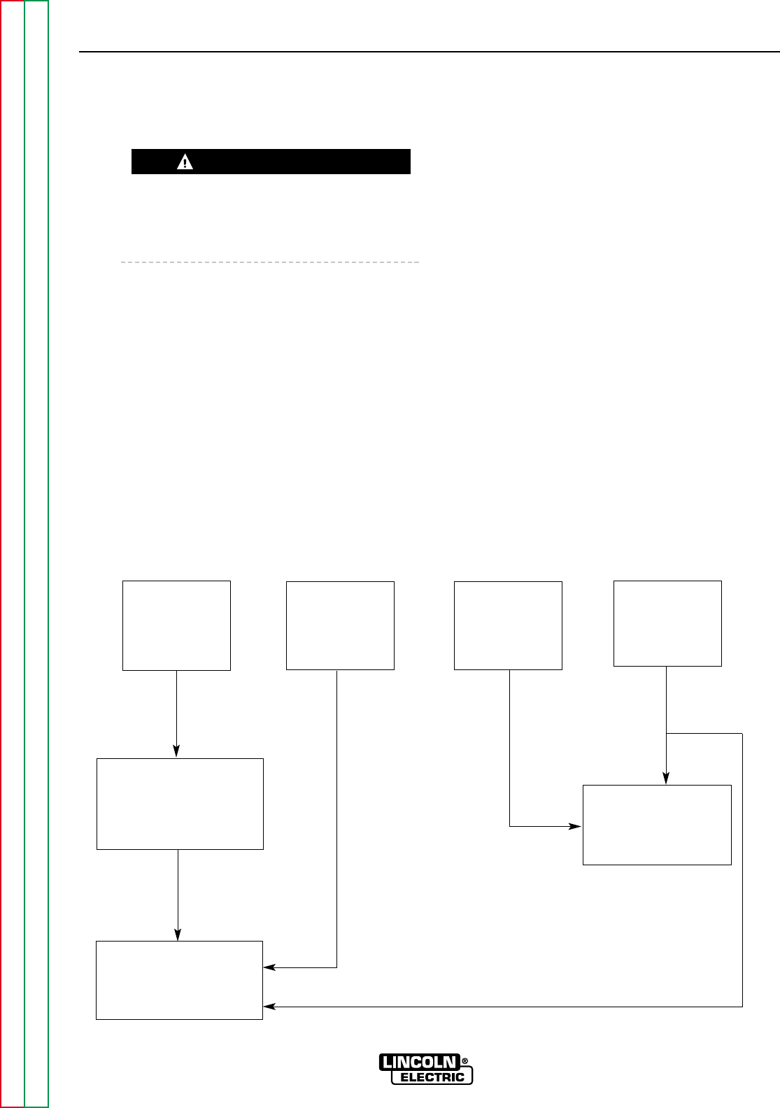
12. Perform appropriate calibration procedure
per flowchart in Figure F.67.
13. Install the PC board cover and tighten the
two screws with the 5/16" nut driver.
14. Install the machine case sides and top.
15. Install the handle and the lift bail rubber
gasket.
POWER WAVE 450
Return to Section TOC Return to Section TOC Return to Section TOC Return to Section TOC
Return to Master TOC Return to Master TOC Return to Master TOC Return to Master TOC
CAUTION
FIGURE F.67 – PC BOARD REPLACEMENT CALIBRATION REQUIREMENTS
DISPLAY
BOARD
REPLACED
IF POSSIBLE
QUICK
VOLTAGE
CALIBRATION
CURRENT
CALIBRATION
FULL
VOLTAGE
CALIBRATION
SNUBBER
BOARD
REPLACED
SHUNT
AMPLIFIER
BOARD
REPLACED
CONTROL
BOARD
REPLACED