


F-60 F-60
FIELD EFFECT TRANSISTOR/SWITCH BOARD TEST
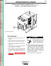
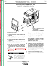
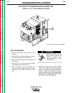
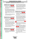
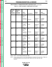
FIGURE F.19 – F.E.T. SWITCH BOARD LOCATION
1
TROUBLESHOOTING & REPAIR
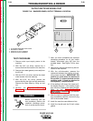
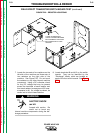
TEST PROCEDURE
1. Remove main input supply power to the
machine.
2. With the 3/8" nut driver, remove the screws
that hold the handle to the machine.
3. Remove the rubber gasket (cover seal) from
the lift bail.
4. With the 5/16" nut driver, remove the sheet
metal screws from the case top.
5. With the 5/16" nut driver, remove the
screws holding the right and left case sides.
Remove the case sides by lifting up and
out.
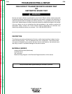
Before continuing with the
test procedure, perform the
following capacitor dis-
charge procedure to avoid
electric shock.
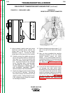
6. Obtain a high resistance and high wattage
resistor (25 - 1000 ohms and 25 watts min-
imum). This resistor is not supplied with the
machine. Secure this resistor to a piece of
insulating material such as a glastic board.
See Figure F.22. NEVER USE A SHORTING
STRAP FOR THIS PROCEDURE.
POWER WAVE 450
Return to Section TOC Return to Section TOC Return to Section TOC Return to Section TOC
Return to Master TOC Return to Master TOC Return to Master TOC Return to Master TOC
WARNING
1. FET OR IGBT SWITCH BOARD ASSEMBLY