


F-180 F-180
DISPLAY BOARD REMOVAL AND REPLACEMENT (continued)
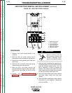
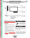
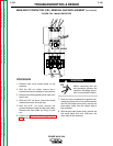
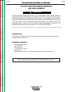
FIGURE F.68 - DISPLAY BOARD REMOVAL
3
4
5
2
1
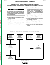
TROUBLESHOOTING & REPAIR
NOTE: Before changing or disturbing the dis-
play board follow the procedure outlined under
QUICK VOLTAGE CALIBRATION (Fig. F.54)
in this section.
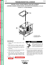
PROCEDURE
1. Remove main input supply power to the
machine.
2. With the 3/8" nut driver, remove the 4
screws that hold the handle to the machine.
3. Remove the rubber gasket (cover seal) from
the lift bail.
4. With the 5/16" nut driver, remove the sheet
metal screws from the case top.
5. With the 5/16" nut driver, remove the
screws holding the right and left case sides.
Remove the case sides by lifting up and
out.
6. Perform the Capacitor Discharge
Procedure described earlier in this section
of the manual.
Before continuing with the
test procedure, perform the
capacitor discharge proce-
dure to avoid electric shock.
Be sure to follow the recommended static-free
methods for handling printed circuit boards.
Failure to do so can result in permanent dam-
age to the equipment.
7. After you have completed the capacitor dis-
charge procedure for all four switch boards,
carefully remove the eight molex plugs from
the lower portion of the display board.
POWER WAVE 450
Return to Section TOC Return to Section TOC Return to Section TOC Return to Section TOC
Return to Master TOC Return to Master TOC Return to Master TOC Return to Master TOC
WARNING
CAUTION
1. MOLEX PLUG HEADERS (8)
2. KEY PAD RIBBON CONNECTOR
3. LCD DISPLAY WINDOW
4. LCD CONNECTOR
5. MOUNTING PIN HOLE