


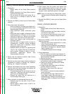
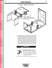
6. Locate the #9 and #12 terminals, identified by the
“Discharge” labels, on each of the four Switch
Boards. See Figure D.2.
7. Using insulated, needle nose-type jumper leads
and insulated gloves, connect one jumper lead to
one end of the resistor obtained in step 4.
Connect the other jumper lead to the other end of
the resistor.
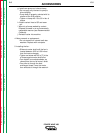
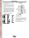
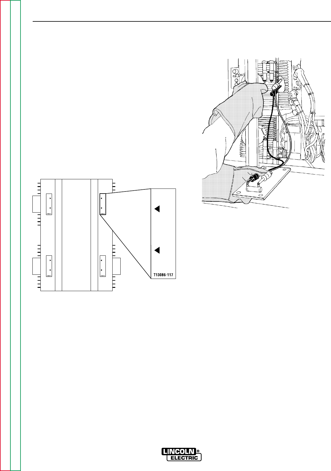
8. Carefully connect the needle nose end of one of
the jumper leads to terminal #9. See Figure D.3.
Connect the needle nose end of the other jumper
lead to terminal #12. Terminals #9 and #12 are
indicated by the “Discharge” label. Leave resistor
connected for 10 seconds. DO NOT TOUCH TER-
MINALS, RESISTORS, OR ANY INTERNAL
MACHINE COMPONENT DURING THIS PROCE-
DURE!
FIGURE D.3 – RESISTORS WITH LEADS
CONNECTED
9. Check voltage across terminals (9 and 12) with a
DC voltmeter. Terminal 9 has positive polarity and
terminal 12 has negative polarity. Voltage should
be zero. If any voltage remains, repeat this capac-
itor discharge procedure.
10. Repeat discharge procedure (steps 7, 8 and 9) for
each of the other three Switch Boards.
MAINTENANCE
D-4 D-4
POWER WAVE 450
Return to Section TOC Return to Section TOC Return to Section TOC Return to Section TOC
Return to Master TOC Return to Master TOC Return to Master TOC Return to Master TOC
D
I
S
C
H
A
R
G
E
D
I
S
C
H
A
R
G
E
D
I
S
C
H
A
R
G
E
D
I
S
C
H
A
R
G
E
D
I
S
C
H
A
R
G
E
FIGURE D.2 – DISCHARGE LABEL