


Return to Section TOC Return to Section TOC Return to Section TOC Return to Section TOC
Return to Master TOC Return to Master TOC Return to Master TOC Return to Master TOC
TROUBLESHOOTING & REPAIR
F-10 F-10
POWER WAVE 450
TROUBLESHOOTING GUIDE Observe Safety Guidelines
detailed in the beginning of this manual.
CAUTION
If for any reason you do not understand the test procedures or are unable to perform the test/repairs safely, con-
tact the Lincoln Electric Service Department for electrical troubleshooting assistance before you proceed. Call 1-
800-833-9353.
PROBLEMS
(SYMPTOMS)
POSSIBLE AREAS OF
MISADJUSTMENT(S)
RECOMMENDED
COURSE OF ACTION
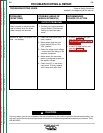
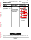
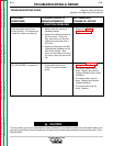
OUTPUT PROBLEMS
Machine has no welding output –
fans run – display is on.
1. Make sure that the machine
was powered up with a proper-
ly installed overlay. Without an
overlay installed in the Power
Wave, or an invalid overlay
installed, the machine will not
have welding output.
2. Check to see if the Limits or
Setup overlay is installed on
the front panel. These two
overlays cannot be used for
welding.
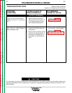
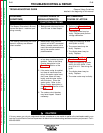
3. Check for proper input voltage
per machine nameplate.
4. Make certain the reconnect
panel is configured properly.
5. Check to see that when the
trigger is pulled on the wire
feeder the wire feeder’s voltage
display changes to indicate arc
voltage. If this does not hap-
pen, the feeder or control
cable may be faulty.
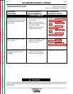
6. Check wire feeder control
cable for loose or faulty con-
nections.
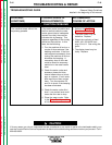
7. If the machine is connected for
380VAC or higher and has not
been used for a long period of
time, the capacitors may
require “conditioning.” Let the
Power Wave run at an idle
state for 30 minutes.
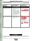
1. Perform the Wire Feeder
Trigger Circuit Test (#1 or #2)
for the appropriate wire feeder
receptacle (amphenol).
2. If a K941-1 Remote Control Kit
is attached to the Power Wave,
then perform the K941-1
Remote Control Kit Trigger
Circuit Test.
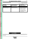
3. Perform the Reconnect
Switch Test #1.
4. Perform the Output Rectifier
Diodes Test.
5. Perform the Switch Board
Test.
6. Perform the Snubber and
Bleeder Resistor Test.
7. Perform the Static Capacitor
Balance Test.
8. Perform the Dynamic
Capacitor Balance Test.