


Return to Section TOC Return to Section TOC Return to Section TOC Return to Section TOC
Return to Master TOC Return to Master TOC Return to Master TOC Return to Master TOC
POWER WAVE 450
F-45 F-45
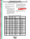
INPUT POWER AND WIRING HARNESS TEST (continued)
TROUBLESHOOTING & REPAIR
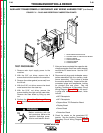
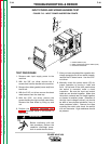
9. Check for shorts or fusing at the input
(top) leads to the main contactor.
10. Remove plug J30 from the protection
board. Check the resistance on the J30
header (the plug mounted on the board)
between pin 1 and pin 6. Resistance
should be very high. If resistance is low or
zero ohms, the protection board is faulty.
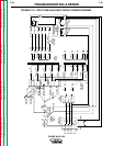
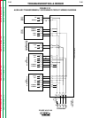
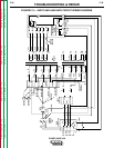
11. Check plug J30 and associated wires for
shorts or damaged connections. See the
Input and Auxiliary Circuit Wiring Diagram,
Figure F.14.
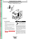
12. If any of the tests reveal signs of heavy
current flow, check the switch boards and
the input rectifier. Refer to the Switch
Board Test and the Input Rectifier
Resistance Test in this section of the
manual.
13. After the test is completed and the prob-
lem successfully repaired, reconnect all
plugs disconnected for the test.
14. Install the PC board cover.
15. Install the machine case sides and top.
16. Install the handle and the lift bail rubber
gasket.