


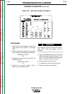

CURRENT CALIBRATION
Service and repair should be performed by only Lincoln Electric factory trained personnel.
Unauthorized repairs performed on this equipment may result in danger to the technician or
machine operator and will invalidate your factory warranty. For your safety and to avoid elec-
trical shock, please observe all safety notes and precautions detailed throughout this manual.
If for any reason you do not understand the test procedures or are unable to perform the
test/repairs safely, contact the Lincoln Electric Service Department for electrical trou-
bleshooting assistance before you proceed. Call 1-800-833-9353 (WELD).
PROCEDURE DESCRIPTION
This procedure is necessary if the control and/or the shunt amplifier boards are replaced. The
current control is the most critical function in the Power Wave machine.
MATERIALS NEEDED
Test and Calibration Overlay L9660-255
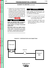
A 300 amp, 30 volt resistance grid load
A small trimmer screwdriver
A calibrated DC ammeter accurate to read 300.0 amps +/- 1.0 amps.
A machine output triggering device such as the K941-1 Remote Control Kit.
SETUP PROCEDURE
1. Remove and install the replacement board in question.
WARNING
TROUBLESHOOTING & REPAIR
F-151 F-151
POWER WAVE 450
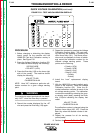
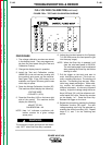
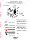
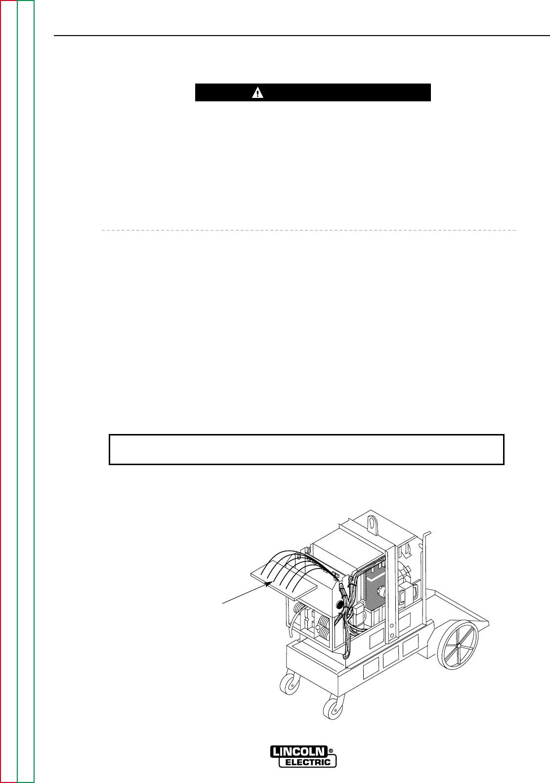
FIGURE F.56 – PC BOARD REMOVED BUT STILL CONNECTED
Lay Control Board on top of machine.
Make sure it is snapped into the ground
plane assembly and insulated from the
case and other components.
Leads
Return to Section TOC Return to Section TOC Return to Section TOC Return to Section TOC
Return to Master TOC Return to Master TOC Return to Master TOC Return to Master TOC
This procedure takes approximately 45 minutes to perform.