


F-189 F-189
OUTPUT RECTIFIER BRIDGE REMOVAL AND REPLACEMENT (continued)
TROUBLESHOOTING & REPAIR
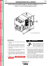
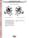
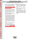
9. Cut all necessary cable ties on the right
side of the machine and disconnect all
necessary leads (two heavy and two small
leads) from the right side of the output
rectifier bridge. Place the fastener hard-
ware back together onto the lead ends to
avoid loss.
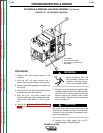
10. On the right side of the machine, use the
7/16" open end wrench to remove the bolt
that connects the heat sink at the top to
the glastic insulated angle mounting
piece. Then remove the carriage bolt that
holds the glastic insulated angle mounting
piece at the bottom to the subframe.
Repeat the same procedure on the left
side of the machine. Save the shake-
proof washers and nuts for reassembly.
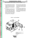
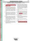
11. With the 7/16" wrench, remove the bolts,
top and bottom, that connect the heat
sink and glastic insulated angle mounting
piece at the middle. With the side bolts
already removed, it is easier to access the
middle bolts.
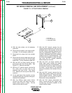
12. With the 7/16" wrench, remove the bolt,
nut, and split-ring lock washer from the
tab connection at the bottom of the heat
sink. The input rectifier bridge can now be
removed. You may have to bend the bot-
tom tab slightly in order to get it past the
main transformer.
POWER WAVE 450
Return to Section TOC Return to Section TOC Return to Section TOC Return to Section TOC
Return to Master TOC Return to Master TOC Return to Master TOC Return to Master TOC
1
4
3
2
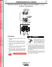
FIGURE F.71 – HEAT SINK REMOVAL
1. GLASTIC INSULATED ANGLE MOUNTING
PIECE (TOP)
2. BOTTOM TAB CONNECTION
3. GLASTIC INSULATED ANGLE MOUNTING
PIECE (BOTTOM)
4. HEAT SINK