


Return to Section TOC Return to Section TOC Return to Section TOC Return to Section TOC
Return to Master TOC Return to Master TOC Return to Master TOC Return to Master TOC
F-100 F-100
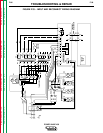
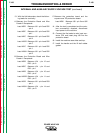
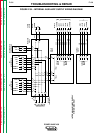
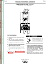
INTERNAL AND AUXILIARY SUPPLY VOLTAGE TEST (continued)
TROUBLESHOOTING & REPAIR
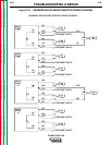
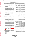
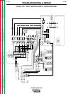
13. With the Volt/ohmmeter, check the follow-
ing leads for continuity:
A. Between the Protection Board and Wire
Feeder 2 Receptacle:
Lead #32D Between J34 - pin 5 and P82
- pin A
Lead #32E Between J34 - pin 6 and P82
- pin I
Lead #42C Between J34 - pin 3 and P82
- pin K
Lead #102D Between J34 - pin 4 and P82
- pin C
Lead #31C Between J34 - pin 1 and P82
- pin J
Lead #106A Between J34 - pin 7 and P82
- pin D
B. Between the Protection Board and Wire
Feeder 1 Receptacle:
Lead #32B Between J34 - pin 12 and
P83 - pin A
Lead #32C Between J34 - pin 13 and
P83 - pin I
Lead #42B Between J34 - pin 10 and
P83 - pin K
Lead #102B Between J34 - pin 11 and
P83 - pin C
Lead #31B Between J34 - pin 8 and P83
- pin J
Lead #105A Between J34 - pin 14 and
P83 - pin D
C. Between the protection board and the
square wave TIG protection board:
Lead #296 Between J38 - pin 3 and J92
- pin 6
14. After the test is completed and the prob-
lem successfully repaired, disconnect
input power to the machine.
15. Connect the five leads to main input con-
tactor CR1 and insert plug J30 into the
protection board.
16. Install the machine case sides and top.
17. Install the handle and the lift bail rubber
gasket.
POWER WAVE 450