


ACCESSORIES
C-3 C-3
POWER WAVE 450
Return to Section TOC Return to Section TOC Return to Section TOC Return to Section TOC
Return to Master TOC Return to Master TOC Return to Master TOC Return to Master TOC
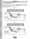
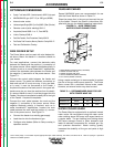
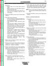
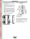
There are two water connections on the rear of the
Power Wave. See Figure C.1. Connect the water lines
between these connectors and those on the wire feed-
er. The water is fed through the feeder into the gun.
When a water cooler is used, the water cooler must be
enabled by using the Setup Overlay.
The water cooler contains a flow switch, which is
closed when there is adequate coolant circulating in
the system. If this flow rate drops below the switch
manufacturer’s set point, the flow switch opens. A cou-
ple of seconds after the flow switch opens the water
cooler shuts down. If the water cooler is enabled and
the flow switch opens, the machine beeps loudly indi-
cating that there is a problem with the water cooler
operation.
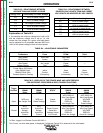
RECOMMENDED COOLANTS
1. The following coolants have been determined to be
compatible with the wetted materials used in the
G3503-[ ] cooler assembly:
• Distilled or deionized water
• Potable tap water
• Sediment-free mixtures containing a maxi-
mum of 50% ethylene glycol or automotive-
grade antifreeze and the balance of distilled
or deionized water.
2. Ethylene glycol mixtures should be selected if the
cooler may be exposed to a temperature below the
freezing point of water.
3. Consult gun, torch, and wire feeder manuals for
coolant recommendations and select one from the
above list.
4. Pure solutions and mixtures of, or materials (i.e.
towels) wetted with ethylene glycol are toxic to
humans and animals. They must not be haphaz-
ardly discarded, especially by pouring liquids down
the drain. Contact the local EPA office for responsi-
ble disposal methods or for recycling information.
5. The cooler’s reservoir has a nominal liquid capaci-
ty of 1.6 gallons.
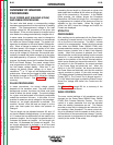
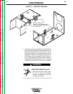
PRIMING THE COOLER
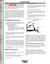
1. Select a recommended coolant and fill cooler to
specified level (see Fig. C.2).
2. Attach desired water-cooled accessory (gun and
wire feeder or TIG torch) to cooler’s QDs.
3. Prime the cooler:
a. Install the Set-up overlay.
b. Keep accessories’ hose lengths horizontal, either
coiled or straight, and no higher than 4 feet of the
specified coolant level.
c. Switch on the Power Wave machine.
d. Press the "WATER COOLER ENABLE" button so
that the "WATER COOLER ENABLED" light is
illuminated.
e. Press the "PRIME WATER COOLER" button until
the "WATER COOLER PRESSURE" light is
steadily illuminated.
4. Check coolant level. Add more if required.
Figure C.2
Do Not Use: Any prepacked welding industry coolant
mixture, such as those offered by Miller, OKI,
Bernhard, or Dynaflux. These coolants contain sub-
stances which attack plastic components and may
shorten the life of the system. Once added, these
substances are virtually impossible to purge from the
system. DO NOT USE OIL-BASED COOLANTS OF
ANY TYPE.
K961-1 Single Cylinder Undercarriage -
Designed for quick installation in the field. Consists of
a front caster assembly, a rear platform assembly, a
handle, and an upper cylinder support.
K962-1 Dual Cylinder Undercarriage -
Designed for quick installation in the field. Consists of
a front caster assembly, a dual bottle rear platform
assembly, a handle, and a dual bottle upper cylinder
support.
0.25 to 0.50
inches
Visible Coolant Level
Rear Panel of
Power Wave
Reservoir Screen