


Return to Section TOC Return to Section TOC Return to Section TOC Return to Section TOC
Return to Master TOC Return to Master TOC Return to Master TOC Return to Master TOC
POWER WAVE 450
F-33 F-33
TROUBLESHOOTING & REPAIR
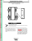
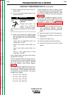
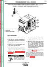
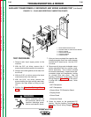
11. To conduct this test, you will be measuring
the voltage between pin 2 and pin 5 of
plug J4. The plug is located in the
machine undercarriage and is somewhat
difficult to reach. It is probably easiest to
disconnect the plug and insert the probes
of your voltmeter alongside pins 2 and 5
before turning on input power, which is the
next step.
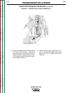
12. Turn the main input supply power to the
machine back ON.
ELECTRIC SHOCK
can kill.
Proceed with caution. Be
careful not to touch any
internal machine components during the
remainder of the test procedure.
13. Check for the correct AC voltage between
plug J4 - pin 2 and J4 - pin 5. It should be
220 - 230 VAC.
If the voltage is correct, then Auxiliary
Transformer #2 is good.
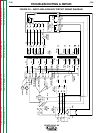
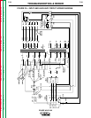
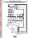
If the voltage is wrong or missing, check the
associated wiring to the transformer primary.
See the Input and Auxiliary Circuit Wiring
Diagram, Figure F.8. These voltages are most
easily checked at the terminal strip. The cor-
rect voltages are as follows:
H1A to H3A = 220 - 230 VAC
If this voltage is wrong or missing, check the
associated wiring to the transformer primary.
If the correct voltage IS applied to the primary
but the voltage at H1A to H3A is not correct,
the transformer may be faulty. Replace the
transformer. Refer to the T2 Auxiliary Trans-
former Removal and Replacement
Procedure in this section of the manual.
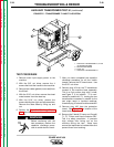
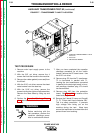
14. After the test is completed and the prob-
lem successfully repaired, reconnect plug
J30 to the protection board.
15. Reconnect plug J73 to the T1 transformer.
16. Reconnect the 5 leads to the main con-
tactor CR1.
17. Install the PC board cover.
18. Install the machine case sides and top.
19. Install the handle and the lift bail rubber
gasket.
WARNING
AUXILIARY TRANSFORMER TEST #2 (continued)