


F-198 F-198
MAIN TRANSFORMER/CHOKE REMOVAL AND REPLACEMENT (continued)
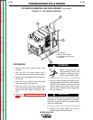
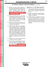
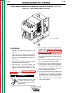
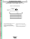
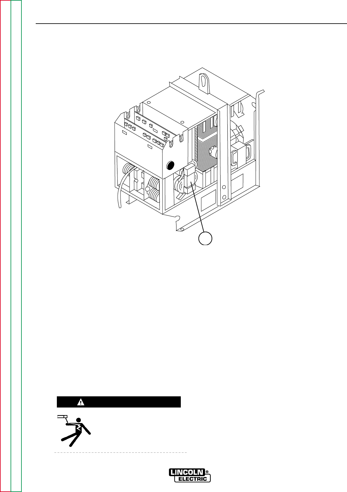
FIGURE F.75 - MAIN TRANSFORMER LOCATION
1
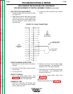
TROUBLESHOOTING & REPAIR
PROCEDURE
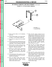
1. Remove main input supply power to the
machine.
2. With the 3/8" nut driver, remove the 4
screws that hold the handle to the machine.
3. Remove the rubber gasket (cover seal) from
the lift bail.
4. With the 5/16" nut driver, remove the sheet
metal screws from the case top.
5. With the 5/16" nut driver, remove the
screws holding the right and left case sides.
Remove the case sides by lifting up and
out.
6. Perform the Capacitor Discharge
Procedure described earlier in this section of
the manual.
Before continuing with the test
procedure, perform the capaci-
tor discharge procedure to avoid
electric shock.
7. After you have completed the capacitor dis-
charge procedure for all four switch boards,
perform the FET Module Assembly
Removal Procedure. Refer to the proce-
dure in this section of the manual. After the
FET module assembly has been removed,
the main transformer and chokes are easily
accessible.
8. With the 3/8" socket wrench, remove the
four main transformer mounting bolts.
9. Disconnect the heavy leads between the
main transformer and the choke assembly.
You will need to cut the cable ties on the
insulating sleeve and slide the sleeve for-
ward to access the connection.
10. Lift the main transformer out. Remove the
background or output chokes if necessary
by removing any mounting bolts holding
the chokes to the machine frame bottom.
11. After reassembly test on high voltage
input and reconnect.
POWER WAVE 450
Return to Section TOC Return to Section TOC Return to Section TOC Return to Section TOC
Return to Master TOC Return to Master TOC Return to Master TOC Return to Master TOC
WARNING
1. MAIN TRANSFORMER