


Return to Section TOC Return to Section TOC Return to Section TOC Return to Section TOC
Return to Master TOC Return to Master TOC Return to Master TOC Return to Master TOC
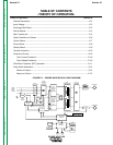
THEORY OF OPERATION
E-5 E-5
POWER WAVE 450
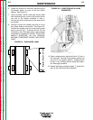
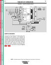
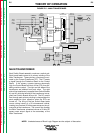
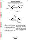
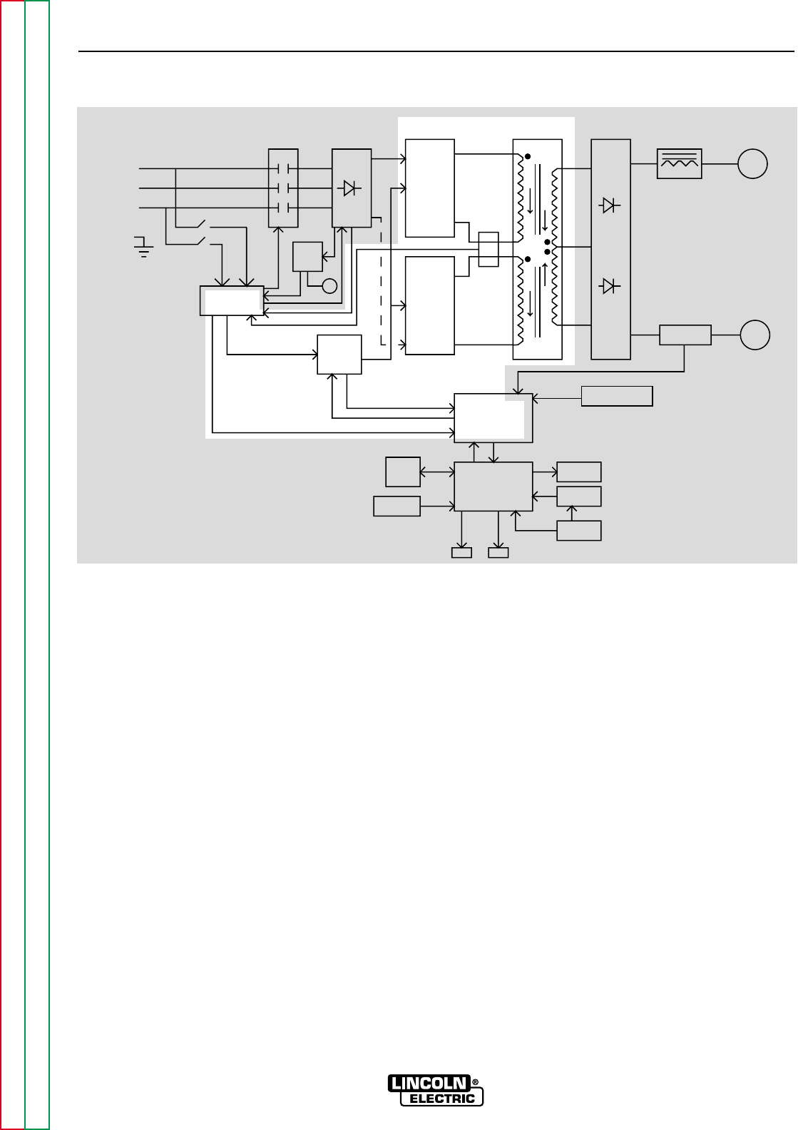
MAIN TRANSFORMER
Each Switch Board assembly works as a switch pair.
Each board feeds current to a primary winding of the
Main Transformer. These primary currents are moni-
tored by the Current Transformer (CT). The CT sends
a signal through the Protection Board to the Control
Board. If the primary currents become abnormally
high, the Control Board will shut off the FETs, thus dis-
abling machine output. The right and left sides of the
transformer are isolated from each other. The right
side of the transformer is supplied from Switch Boards
#1 and #2, while the left side of the transformer is sup-
plied from Switch Boards #3 and #4. The DC current
flow through each primary winding is clamped back to
each respective input capacitor when the FETs are
turned off. The firing of the four Switch Board pairs
occurs during halves of a 50 microsecond interval,
creating two constant 20 kHz square waves on the pri-
mary side of the transformer. The current flow through
the Main Transformer primaries induces a 20 kHz AC
square wave output signal at the secondary of the
Main Transformer.
FIGURE E.5 – MAIN TRANSFORMER
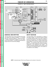
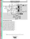
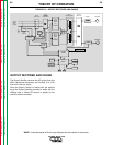
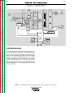
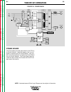
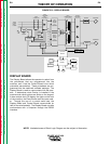
NOTE: Unshaded areas of Block Logic Diagram are the subject of discussion.
CONTROL
BOARD
DISPLAY
BOARD
PROTECTION
BOARD
AUX.
TRANS
POWER
BOARD
CT
CONTACTOR
INPUT
INPUT
RECTIFIER
AND
RECONNECT
SWITCH
BOARD
FET
ASSEMBLY
SWITCH
BOARD
FET
ASSEMBLY
MAIN
TRAMSFORMER
OUTPUT
RECTIFIER
SHUNT
CHOKE POSITIVE
NEGATIVE
SNUBBER AND
LEADS
SENSE
LCD
DISPLAY
KEYPAD
OVERLAY
WATER
COOLER
PC
INTERFACE
INPUT
LINE
SWITCH
FAN
WF1 WF2
THREE
PHASE
INPUT
POWER
LEFT
RIGHT