


Return to Section TOC Return to Section TOC Return to Section TOC Return to Section TOC
Return to Master TOC Return to Master TOC Return to Master TOC Return to Master TOC
MAINTENANCE
D-3 D-3
POWER WAVE 450
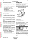
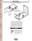
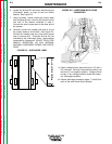
FIGURE D.1 – RESISTOR LOCATIONS
WARNING
5. Locate two sets of two resistors on the left side of
the machine and three sets of two resistors on the
right side of the machine. See Figure D.1. Do not
touch the resistors or any other internal machine
component. Using a DC voltmeter, check for any
DC voltage that may be present across the termi-
nals of each resistor and from each resistor to
case ground (20 measurements in all). If a voltage
is present, be careful not to touch these resistors.
ELECTRIC SHOCK can kill.
• Proceed with caution being care-
ful not to touch any internal
machine components during the
discharge procedure.
5 PAIRS OF RESISTORS
CHECK VOLTAGES BETWEEN EACH
TERMINAL AND FROM EACH RESISTOR
TO CASE GROUND