


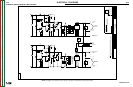
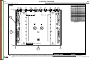
ELECTRICAL DIAGRAMS
G-24 G-24
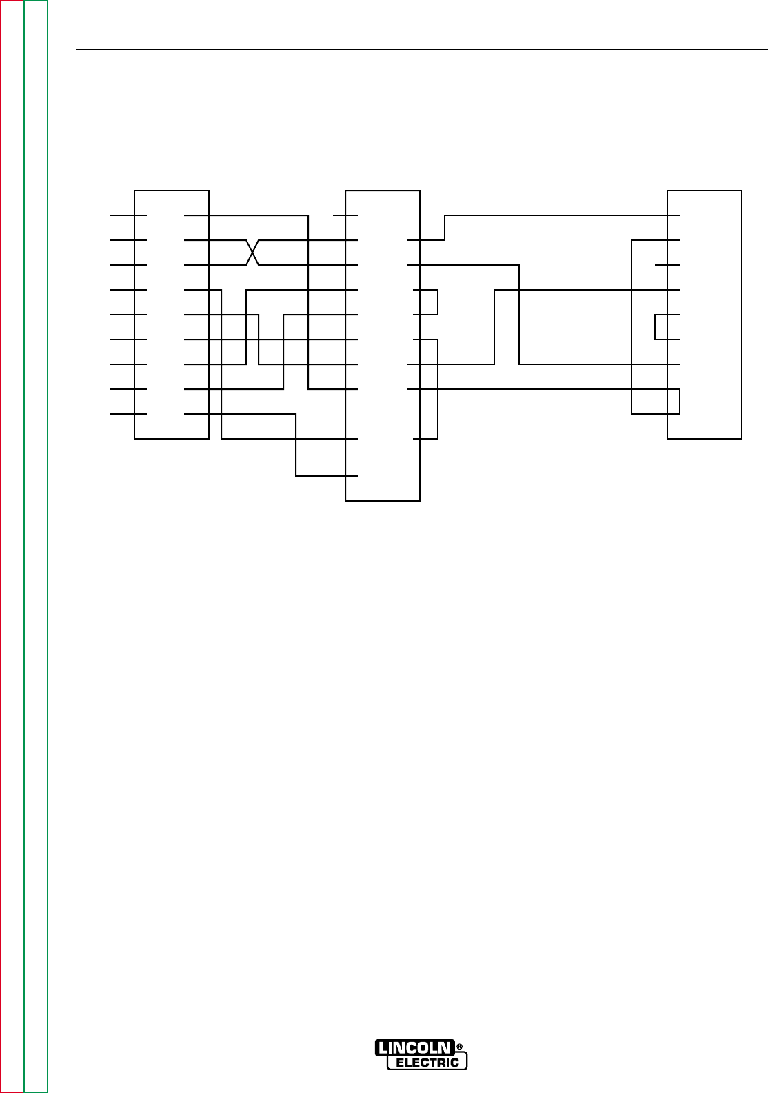
POWER WAVE 450
Return to Section TOC Return to Section TOC Return to Section TOC Return to Section TOC
Return to Master TOC Return to Master TOC Return to Master TOC Return to Master TOC
1
2
3
4
5
6
7
8
9
DCD
RD
TD
DTR
GND
DSR
RTS
CTS
RI
2
3
4
5
6
7
8
20
22RI
TD
RD
RTS
CTS
DSR
GND
DCD
DTR
1 1
2
3
4
5
6
7
8
9
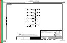
#302
#306
#303
#307
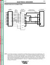
9 PIN
FROM PC
NULL
MODEM
CABLE
RS 232
POWER WAVE
INTERNAL WIRING
J17 MOLEX
DISPLAY BOARD
CONNECTOR
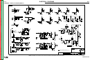
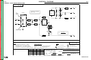
POWER WAVE RS 232 CONNECTIONS
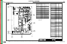
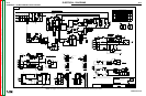
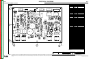
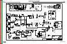
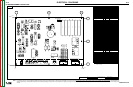
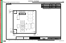
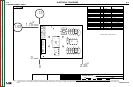
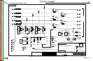
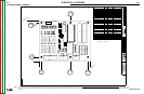
NOTE: Lincoln Electric assumes no responsibility for liabilities resulting from board level troubleshooting. PC
Board repairs will invalidate your factory warranty. This Printed Circuit Board schematic is provided for
reference only. It may not be totally applicable to your machine’s specific PC board version. This dia-
gram is intended to provide general information regarding PC board function. Lincoln Electric discour-
ages board level troubleshooting and repair since it may compromise the quality of the design and may
result in Danger to the Machine Operator or Technician. Improper PC board repairs could result in
damage to the machine.