


Return to Section TOC Return to Section TOC Return to Section TOC Return to Section TOC
Return to Master TOC Return to Master TOC Return to Master TOC Return to Master TOC
F-109 F-109
SERIAL LOOP WIRING HARNESS TEST (continued)
TROUBLESHOOTING & REPAIR
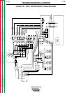
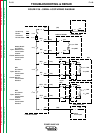
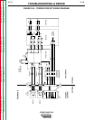
B. Check for loose or broken leads between
the following pins:
P83 - pin L and J27 - pin 1 on the control
board (lead #111A)
P83 - pin M and J27 - pin 4 on the control
board (lead #112A)
C. Make sure that plug J27 is plugged into
the control board securely and that none of
its pins are loose.
D. Reconnect the wire feeder to the wire
feeder 1 amphenol (P83).
9. Perform the following test for faults on the
serial loop circuitry between wire feeder 2
amphenol (P82) and the control board.
A. Disconnect the wire feeder from the wire
feeder 2 amphenol (P82).
B. Check for loose or broken leads between
the following pins:
P82 - pin L and J28 - pin 1 on the control
board (lead #117A)
P82 - pin M and J28 - pin 4 on the control
board (lead #118A)
C. Make sure that plug J28 is plugged into
the control board securely and that none of
its pins are loose.
D. Reconnect the wire feeder to the wire
feeder 2 amphenol (P82).
10. Perform the following test for faults on the
serial loop circuitry between the display
board and the control board.
A. Check for loose or broken leads between
the following pins:
J26 - pin 3 on the control board and J14 -
pin 6 on the display board (lead #263)
J26 - pin 4 on the control board and J14 -
pin 3 on the display board (lead #264)
B. Make sure that plug J26 is plugged into
the control board securely and that none of
its pins are loose. Also make sure that
plug J14 is securely plugged into the dis-
play board and that none of its pins are
loose.
11. Perform the following test for faults on the
serial loop circuitry 40 mA current supply.
A. Check for loose or broken leads between
the following pins:
J22 - pin 5 on the control board and J44 -
pin 5 on the power board (lead #5R)
J22 - pin 4 on the control board and J44 -
pin 4 on the power board (lead #5W)
B. Make sure that plug J22 is plugged into
the control board securely and that none of
its pins are loose. Also make sure that
plug J44 is securely plugged into the
power board and that none of its pins are
loose.
With the DC voltmeter, check for at least 30
VDC between plug J44 - pin 5 and pin 4 on the
power board. This is the voltage source for the
40 mA current for the serial loop. If the voltage
is low or not present, the power board may be
faulty. Replace the power board.
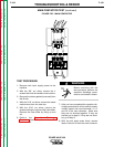
12. After the test is completed and the prob-
lem successfully repaired, replace the PC
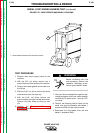
board cover with two sheet metal screws.
13. Install the machine case sides and top.
14. Install the handle and the lift bail rubber
gasket.
POWER WAVE 450
1/96