


CONTROL
BOARD
DISPLAY
BOARD
PROTECTION
BOARD
AUX.
TRANS
POWER
BOARD
CT
CONTACTOR
INPUT
INPUT
RECTIFIER
AND
RECONNECT
SWITCH
BOARD
FET
ASSEMBLY
SWITCH
BOARD
FET
ASSEMBLY
MAIN
TRAMSFORMER
OUTPUT
RECTIFIER
SHUNT
CHOKE POSITIVE
NEGATIVE
SNUBBER AND
LEADS
SENSE
LCD
DISPLAY
KEYPAD
OVERLAY
WATER
COOLER
PC
INTERFACE
INPUT
LINE
SWITCH
FAN
WF1 WF2
THREE
PHASE
INPUT
POWER
LEFT
RIGHT
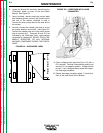
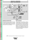
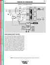
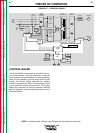
GENERAL DESCRIPTION
The Power Wave is an inverter type power source that
can support most welding procedures. It is modeled
after a P.C. (Personal Computer). There are no specif-
ic welding characteristics designed into the power
portion of the machine. All welding characteristics are
programmed into the software package.
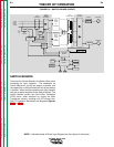
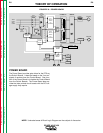
INPUT VOLTAGE
The Power Wave can be connected for a variety of
three phase voltages. The initial input power is applied
to the Power Wave through a line switch located on
the front of the machine. The voltage is connected to
the Protection Board where it is current limited before
being passed on to the input rectifier and reconnect
switches. The reconnect panel allows the user to
switch to low or high voltage and connect the Auxiliary
Transformer to the appropriate input voltage. The
Auxiliary Transformer supplies power to the fan motors
and, through the Protection Board, to the printed cir-
cuit boards and wire feeder(s).
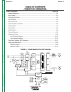
THEORY OF OPERATION
E-2 E-2
POWER WAVE 450
Return to Section TOC Return to Section TOC Return to Section TOC Return to Section TOC
Return to Master TOC Return to Master TOC Return to Master TOC Return to Master TOC
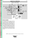
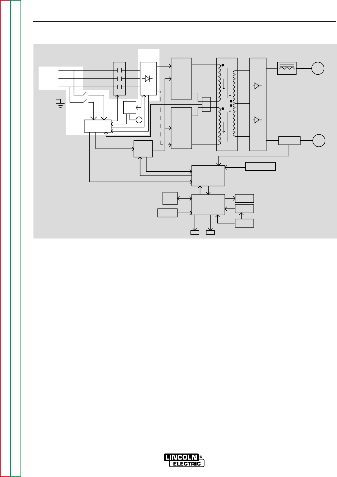
FIGURE E.2 – INPUT VOLTAGE CIRCUIT
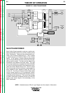
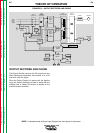
NOTE: Unshaded areas of Block Logic Diagram are the subject of discussion.