


F-156 F-156
T1 AUXILIARY TRANSFORMER REMOVAL AND REPLACEMENT (continued)
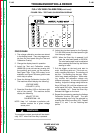
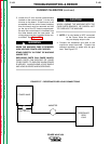
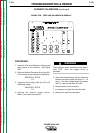
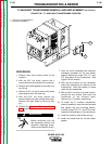
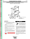
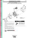
FIGURE F.59 - T1 AUXILIARY TRANSFORMER LOCATION
1
2
TROUBLESHOOTING & REPAIR
PROCEDURE
1. Remove main input supply power to the
machine.
2. With the 3/8" nut driver, remove the 4
screws that hold the handle to the machine.
3. Remove the rubber gasket (cover seal) from
the lift bail.
4. With the 5/16" nut driver, remove the sheet
metal screws from the case top.
5. With the 5/16" nut driver, remove the
screws holding the right and left case sides.
Remove the case sides by lifting up and
out.
6. Perform the Capacitor Discharge Proce-
dure described earlier in this section of the
manual.
Before continuing with the
test procedure, perform the
capacitor discharge proce-
dure to avoid electric shock.
7. After you have completed the capacitor
discharge procedure for all four switch
boards, disconnect plugs P70, P71, and
P73 that attach to the transformer. See
Figure F.59 for location.
8. With the wire cutters, cut any necessary
cable ties (necessary for removal of the
transformer). Note the location of these
cable ties for reassembly.
9. With the 3/8" nut driver or socket wrench,
remove the two screws that mount the
transformer to the machine base.
Remove the T1 auxiliary transformer.
10. To install the T1 auxiliary transformer,
carefully position it onto the machine base
and tighten the two mounting screws.
Connect plugs P70, P71, and P73 to their
respective receptacles on the transformer.
11. Install the machine case sides and top.
12. Install the handle and the lift bail rubber
gasket.
POWER WAVE 450
Return to Section TOC Return to Section TOC Return to Section TOC Return to Section TOC
Return to Master TOC Return to Master TOC Return to Master TOC Return to Master TOC
WARNING
1. AUXILIARY TRANSFORMER T1
2. MOUNTING SCREW (2)