


F-181 F-181
DISPLAY BOARD REMOVAL AND REPLACEMENT (continued)
TROUBLESHOOTING & REPAIR
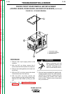
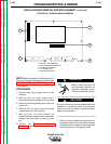
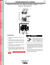
8. Carefully remove the key pad ribbon con-
nector from the right side of the display
board.
9. Carefully remove the connector to the LCD
display.
Do not touch the sensors located on the left
side of the display board when you handle it
for removal or replacement. Failure to do so
can result in permanent damage to the sen-
sors.
10. Carefully remove the display board from
the its mounting pins. Remove the display
board by lifting up and out.
11. Reinstall the display board by carefully
pressing it onto its mounting pins. Install
the LCD display connector, the key pad
connector, and the eight molex plugs that
fit along the bottom portion of the display
board.
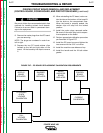
12. After you have installed the display board
(a new one or the old one), you must per-
form the Display Board Sensor
Calibration Test and necessary voltage
calibration. Refer to this test in the test
portion of this section of the manual.
13. After performing the Display Board
Sensor Calibration Test, install the
machine case sides and top.
14. Install the handle and the lift bail rubber
gasket.
POWER WAVE 450
Return to Section TOC Return to Section TOC Return to Section TOC Return to Section TOC
Return to Master TOC Return to Master TOC Return to Master TOC Return to Master TOC
CAUTION