


F-108 F-108
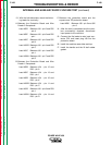
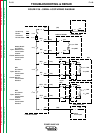
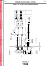
SERIAL LOOP WIRING HARNESS TEST (continued)
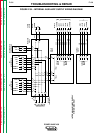
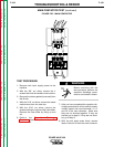
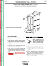
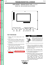
FIGURE F.37 - WIRE FEEDER AMPHENOL LOCATIONS
1
TROUBLESHOOTING & REPAIR
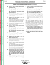
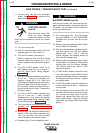
TEST PROCEDURE
1. Remove main input supply power to the
machine.
2. With the 3/8" nut driver, remove the 4
screws that hold the handle to the machine.
3. Remove the rubber gasket (cover seal) from
the lift bail.
4. With the 5/16" nut driver, remove the sheet
metal screws from the case top.
5. With the 5/16" nut driver, remove the
screws holding the right and left case sides.
Remove the case sides by lifting up and
out.
6. Perform the Capacitor Discharge
Procedure described earlier in this section
of the manual.
Before continuing with the
test procedure, perform the
capacitor discharge proce-
dure to avoid electric shock.
7. After you have completed the capacitor dis-
charge procedure for all four switch boards,
remove the PC board cover. Use the 5/16"
nut driver.
8. Perform the following test for faults on the
serial loop circuitry between wire feeder 1
amphenol (P83) and the control board.
A. Disconnect the wire feeder from the wire
feeder 1 amphenol (P83).
POWER WAVE 450
Return to Section TOC Return to Section TOC Return to Section TOC Return to Section TOC
Return to Master TOC Return to Master TOC Return to Master TOC Return to Master TOC
WARNING
1. WIRE FEEDER CONNECTIONS (ON BACK PANEL)