


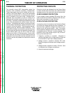
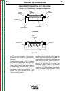
An FET is a type of transistor. FETs are semi-
conductors well suited for high-frequency
switching.
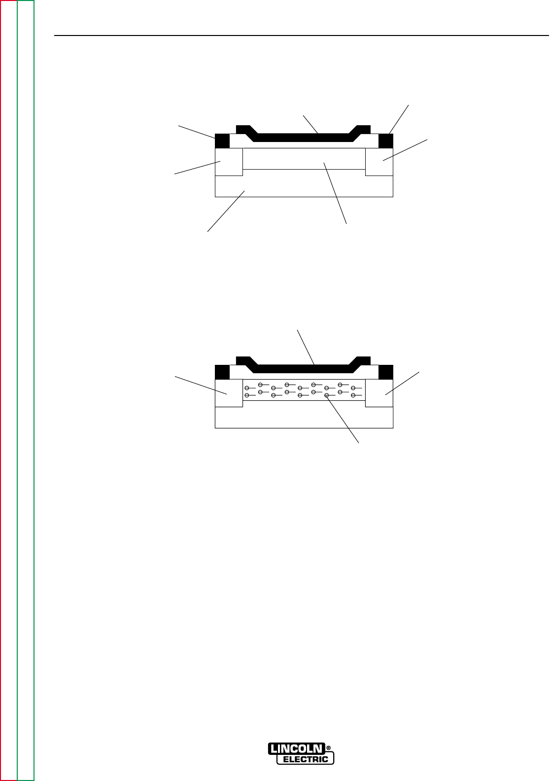
Drawing A above shows an FET in a passive
mode. There is no gate signal (zero volts) from
the source and, therefore, no current flow. The
drain terminal of the FET may be connected to
a voltage supply. But since there is no con-
duction, the circuit will not supply current to
downstream components connected to the
source. The circuit is turned off like a light
switch in the OFF position.
Drawing B above shows the FET in an active
mode. When the gate signal, a positive DC
voltage relative to the source, is applied to the
gate terminal of the FET, it can’t conduct cur-
rent. A voltage supply connected to the drain
terminal will allow the FET to conduct and
henceforth supply current to downstream
components. Current will flow through the
conducting FET to downstream components
as long as the gate signal is present. This is
similar to turning on a light switch.
THEORY OF OPERATION
E-11 E-11
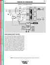
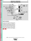
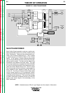
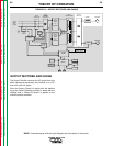
POWER WAVE 450
Return to Section TOC Return to Section TOC Return to Section TOC Return to Section TOC
Return to Master TOC Return to Master TOC Return to Master TOC Return to Master TOC
FIELD EFFECT TRANSISTOR (FET) OPERATION
FIGURE E.10 – FIELD EFFECT TRANSISTOR OPERATION
SUBSTRATE (P)
GATE
TERMINAL
(+ 6 VOLTS)
GATE
TERMINAL
(0 VOLTS)
DRAIN (N)
DRAIN (N)
DRAIN
TERMINAL
SOURCE
TERMINAL
ELECTRONS
SOURCE (N)
SOURCE (N)
N CHANNEL
A. PASSIVE
B. ACTIVE