


F-62 F-62
FIELD EFFECT TRANSISTOR/SWITCH BOARD TEST (continued)
D
I
S
C
H
A
R
G
E
D
I
S
C
H
A
R
G
E
D
I
S
C
H
A
R
G
E
D
I
S
C
H
A
R
G
E
D
I
S
C
H
A
R
G
E
TROUBLESHOOTING & REPAIR
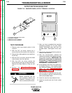
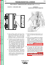
9. Using insulated, needle nose type jumper
leads and insulated gloves, connect one
jumper lead to one end of the resistor
obtained in step 6. Connect the other
jumper lead to the other end of the resistor.
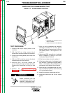
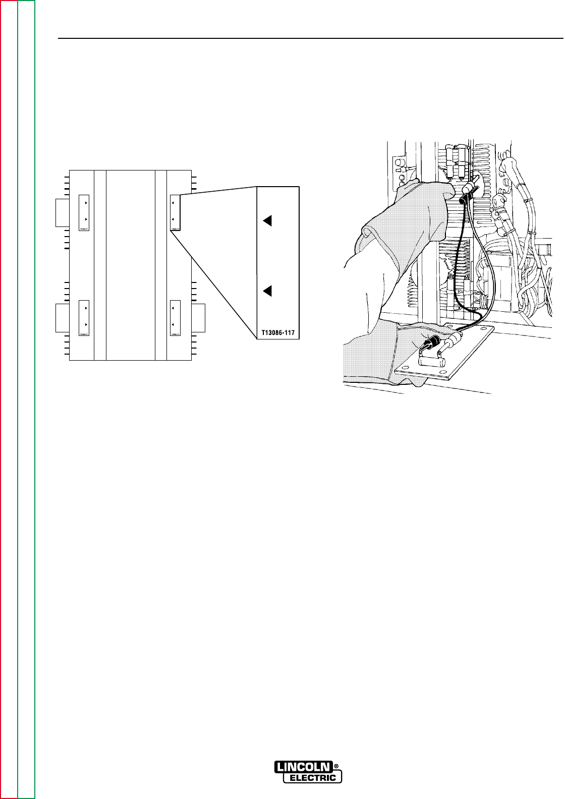
10. Carefully connect the needle nose end of
one of the jumper leads to terminal #9.
See Figure F.22. Connect the needle nose
end of the other jumper lead to terminal
#12. Terminals #9 and #12 are indicated
by the "Discharge" label. Leave the resis-
tor connected for 10 seconds. DO NOT
TOUCH TERMINALS, RESISTORS, OR
ANY INTERNAL MACHINE COMPO-
NENTS DURING THIS PROCEDURE!
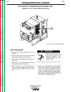
11. Check the voltage across terminals #9 and
#12 with the DC voltmeter. Terminal #9
has positive polarity and terminal #12 has
negative polarity. Voltage should be zero.
If any voltage remains, repeat this capaci-
tor discharge procedure.
12. Repeat discharge procedure steps 9, 10,
and 11 for each of the other three switch
boards.
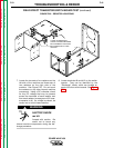
13. After you have completed the capacitor
discharge procedure for all four switch
boards, Visually inspect the switch
boards. If any of them appear burned or
overheated, replace all four switch boards
and input filter capacitors C1, C2, C3, and
C4. Refer to the FET Module Assembly
Removal and Replacement Procedure
in this section of the manual.
14. If none of the switch boards shows physi-
cal damage, test each switch board
according to the procedures given below.
If any test shows that one of the switch
boards is damaged, replace all four switch
boards and input filter capacitors C1, C2,
C3, and C4. Refer to the FET Module
Assembly Removal and Replacement
Procedure in this section of the manual.
POWER WAVE 450
Return to Section TOC Return to Section TOC Return to Section TOC Return to Section TOC
Return to Master TOC Return to Master TOC Return to Master TOC Return to Master TOC
FIGURE F.21 - DISCHARGE LABEL FIGURE F.22
RESISTOR WITH LEADS CONNECTED