


F-195 F-195
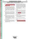
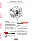
FET MODULE REMOVAL AND REPLACEMENT (continued)
TROUBLESHOOTING & REPAIR
30. Install the water cooler assembly. Refer to
the Water Cooler Removal and Replace-
ment Procedure in this section of the
module.
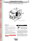
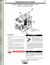
31. With the 7/16" wrench, connect the heavy
current-carrying flat copper strap running
from the shunt amplifier to the output rec-
tifier bridge. With a 5/16" wrench, install
the two sheet metal screws holding the
subframe bottom support section.
Connect the green ground lead on the left
side.
32. Swing the back of the subframe into
place. With the 5/16" nut driver, install the
sheet metal screw holding the ground
leads to the right rear of the subframe. On
the left side, clip the cable tie to hold the
leads.
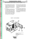
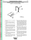
33. With the 3/8" wrench, install the six resis-
tors that are attached to the top of the
subframe (four on the top right, two on the
top left) according to the markings you
made during disassembly. Also tighten
the bottom resistors closest to the FET
module assembly.
34. With the Phillips head screw driver, install
the screw that holds the piezo-electric
alarm buzzer in place. Replace the cable
tie that holds the wire.
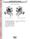
35. Slide the lift bail into place. With the 1/2"
socket wrench, install the four bolts (two
on each side of the machine) to secure the
lift bail. With the 3/8" nut driver, install the
two screws to secure the lift bail baffle.
Feed the output cable strap through the
lift bail baffle eyelet hole. Replace any
necessary cable ties.
36. Connect the two plugs to the snubber
board.
37. Connect the leads to the output rectifier
bridge. Replace all necessary cable ties.
38. Install the molex plugs to the PC boards.
Refer to Figure F.1, PC Board Connector
Locations in this section of the manual.
39. Install the printed circuit board cover with
two 5/16" screws.
40. Replace any necessary cable ties for the
wiring harness and other leads that were
cut during disassembly.
41. Install the machine case sides and top.
42. Install the handle and the lift bail rubber
gasket.
43. Prior to applying full input power perform
the Pre-Power Up Switch Board Test.
POWER WAVE 450
Return to Section TOC Return to Section TOC Return to Section TOC Return to Section TOC
Return to Master TOC Return to Master TOC Return to Master TOC Return to Master TOC