


F-168 F-168
FAN MOTOR REMOVAL AND REPLACEMENT (continued)
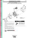
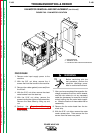
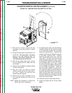
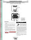
FIGURE F.63 - FAN MOTOR LOCATION
1
2
3
TROUBLESHOOTING & REPAIR
PROCEDURE
1. Remove main input supply power to the
machine.
2. With the 3/8" nut driver, remove the 4
screws that hold the handle to the machine.
3. Remove the rubber gasket (cover seal) from
the lift bail.
4. With the 5/16" nut driver, remove the sheet
metal screws from the case top.
5. With the 5/16" nut driver, remove the
screws holding the right and left case sides.
Remove the case sides by lifting up and
out.
6. Perform the Capacitor Discharge
Procedure described earlier in this section
of the manual.
Before continuing with the
test procedure, perform the
capacitor discharge proce-
dure to avoid electric shock.
7. After you have completed the capacitor dis-
charge procedure for all four switch boards,
use the wire cutters to cut any necessary
cable ties (necessary for removal of the fan
motor) holding the fan motor leads togeth-
er. Note the location of these cable ties for
reassembly.
8. Remove the fan motor leads from the ter-
minal strip.
9. With the 5/16" nut driver, remove the water
cooler access door. Then remove the four
screws from the lower rear panel.
POWER WAVE 450
Return to Section TOC Return to Section TOC Return to Section TOC Return to Section TOC
Return to Master TOC Return to Master TOC Return to Master TOC Return to Master TOC
WARNING
1. MACHINE BACK
2. TERMINAL STRIP
3. FAN MOTOR AND MOUNTING BRACKET