


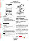

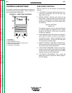
CONTROLS AND SETTINGS
All operator controls and adjustments are located on
the case front of the Power Wave. Refer to Figure B.1
and corresponding explanations.
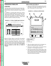
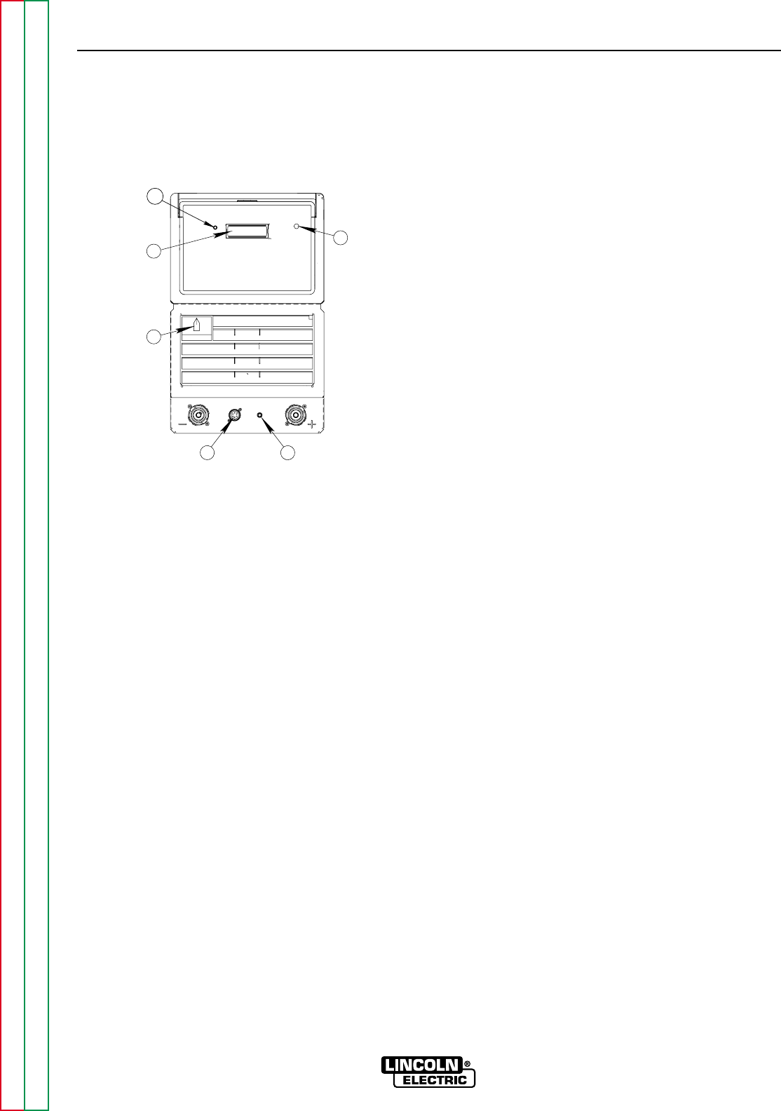
FIGURE B.1 – CASE FRONT CONTROLS
CASE FRONT CONTROLS
Refer to Figure B.1 for the location of the following
controls:
1. LCD DISPLAY: Provides welding procedure infor-
mation and parameters such as wire type, gas
type, WFS, trim, etc.
2. POWER SWITCH: Controls input power to the
Power Wave. When the switch is turned to the ON
position, the connected wire feeder meters light
up and the LCD display on the Power Wave shows
the following:
LINCOLN ELECTRIC
Version X.X
This display is shown for a few seconds followed
by another display that depends on the overlay
placed on the machine. At this point, the machine
is ready for operation.
3. HIGH TEMPERATURE LIGHT (thermal overload): A
yellow light that comes on when an over tempera-
ture situation occurs. Output is disabled until the
machine cools down. At that point the light goes
out and output is enabled again.
4. REMOTE CONTROL AMPHENOL RECEPTACLE:
Allows remote current control during stick welding
via a hand or foot Amptrol accessory.
5. 5 AMP CIRCUIT BREAKER: Protects two auxiliary
power circuits: the 24V supply used by the trigger
circuits and the 42V supply used by the internal
machine circuits and the wire feeders.
6. LCD DISPLAY ADJUSTMENT: Use a small flat
blade screw driver to adjust the viewing angle of
the LCD display.
OPERATION
B-5 B-5
POWER WAVE 450
Return to Section TOC Return to Section TOC Return to Section TOC Return to Section TOC
Return to Master TOC Return to Master TOC Return to Master TOC Return to Master TOC
1
3
5
4
2
6
1 LCD DISPLAY
2 POWER SWITCH
3 HIGH TEMPERATURE LIGHT
4 REMOTE CONTROL AMPHENOL RECEPTACLE
5 5 AMP CIRCUIT BREAKER
6 LCD DISPLAY ADJUSTMENT