


Return to Section TOC Return to Section TOC Return to Section TOC Return to Section TOC
Return to Master TOC Return to Master TOC Return to Master TOC Return to Master TOC
F-98 F-98
INTERNAL AND AUXILIARY SUPPLY VOLTAGE TEST (continued)
TROUBLESHOOTING & REPAIR
TEST PROCEDURE
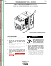
1. Remove main input supply power to the
machine.
2. With the 3/8" nut driver, remove the 4
screws that hold the handle to the machine.
3. Remove the rubber gasket (cover seal) from
the lift bail.
4. With the 5/16" nut driver, remove the sheet
metal screws from the case top.
5. With the 5/16" nut driver, remove the
screws holding the right and left case sides.
Remove the case sides by lifting up and
out.
6. Perform the Capacitor Discharge
Procedure described earlier in this section
of the manual.
Before continuing with the test procedure, per-
form the capacitor discharge procedure to
avoid electric shock.
7. After you have completed the capacitor dis-
charge procedure for all four switch boards,
remove the PC board cover. Use the 5/16"
nut driver.
8. Remove the 5 leads ( 3 heavy and 2 small)
T1, T2, T3 from main input contactor CR1.
This is a safety precaution. It prevents high
voltage from being put on the machine dur-
ing the test. Wrap tape around the lead
ends to insulate them and prevent them
from touching.
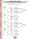
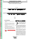
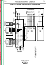
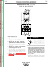
9. Remove plug J30 from the protection
board. See Figure F.1 for location of the
board and plug J30.
10. Make sure that none of the pins are loose
or open on the following molex plugs: J33,
J34, J35, J37, J38 (on the protection
board), J12, J13, J16 (on the display
board), J22 (on the control board), J42,
J43, and J44 (on the power board). See
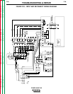
the Internal Auxiliary Supply Wiring
Diagram, Figure F.34.
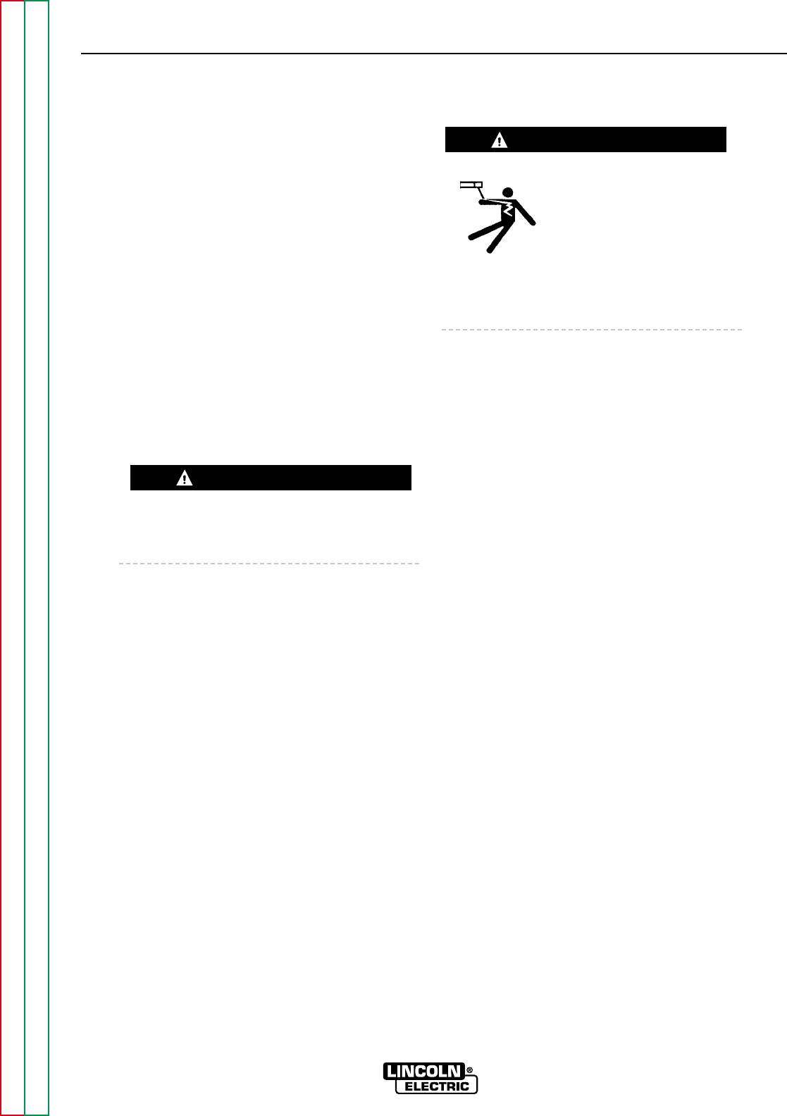
ELECTRIC SHOCK
can kill.
With input power ON, there
are high voltages inside the
machine, including plug J30
and the protection board. Do not reach into
the machine or touch any internal part of the
machine while power is ON.
11. Turn input power ON. Machine output
must be OFF.
12. Verify the following voltage measure-
ments:
A. Protection Board:
115 VAC Between J33 - pin 6 and J33 -
pin 1 (Power Wave 450 only)
42 VAC Between J33 - pin 3 and J33 -
pin 1
24 VAC Between J33 - pin 4 and J33 -
pin 1
If any of these voltages are not present on the
protection board, and the Auxiliary Transformer
1 Test has been completed successfully, do
the following: Turn the power switch SW1 OFF
and disconnect input power to the machine.
Check the pins of plug J33 to be sure they are
not loose or broken. Since Auxiliary
Transformer 1 Test determined that voltages
are present at plug J33, the fault must be that
these signals are not getting to header J33.
B. Protection Board:
115 VAC Between J34 - pin 1 and J34 -
pin 5 (Power Wave 450 only)
42 VAC Between J34 - pin 3 and J34 -
pin 5
24 VAC Between J34 - pin 4 and J34 -
pin 5
If any of these voltages are not present on the
protection board (and the voltages in part A,
above, were present, replace the protection
board.
POWER WAVE 450
WARNING
WARNING