


F-104 F-104
MAIN CONTACTOR TEST (continued)
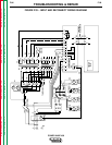
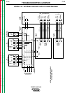
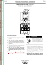
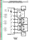
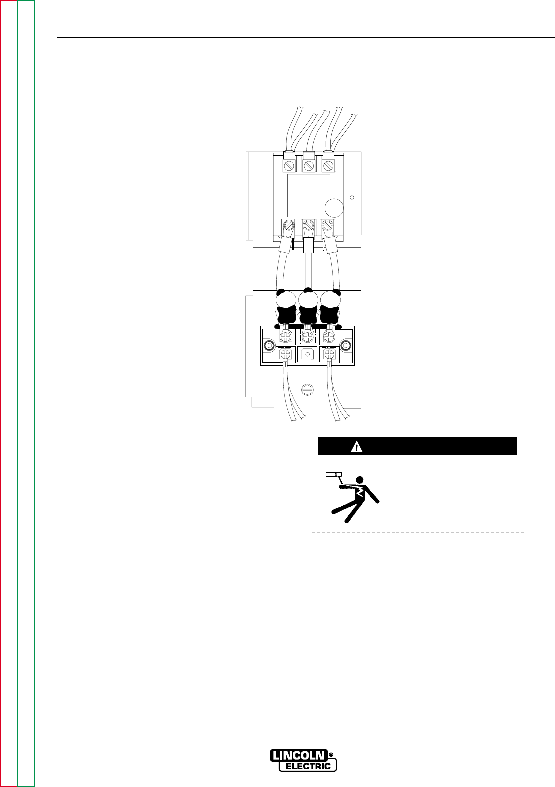
FIGURE F.35 - MAIN CONTACTOR
CR1
L
1
A
L1 L2 L3
T1 T2 T3
L
3
A
TROUBLESHOOTING & REPAIR
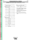
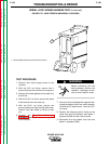
TEST PROCEDURE
1. Remove main input supply power to the
machine.
2. With the 3/8" nut driver, remove the 4
screws that hold the handle to the machine.
3. Remove the rubber gasket (cover seal) from
the lift bail.
4. With the 5/16" nut driver, remove the sheet
metal screws from the case top.
5. With the 5/16" nut driver, remove the
screws holding the right and left case sides.
Remove the case sides by lifting up and
out.
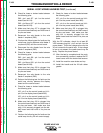
6. Perform the Capacitor Discharge
Procedure described earlier in this section
of the manual.
Before continuing with the
test procedure, perform the
capacitor discharge proce-
dure to avoid electric shock.
7. After you have completed the capacitor dis-
charge procedure for all four switch boards,
visually inspect the input terminals L1, L2,
and L3 of the main contactor. Make sure
they are not shorted together. If they are
shorted, go to step 8. If they are not short-
ed, go to step 9.
8. With the slot head screw driver, remove
leads L1A and L3A from the main contactor.
POWER WAVE 450
Return to Section TOC Return to Section TOC Return to Section TOC Return to Section TOC
Return to Master TOC Return to Master TOC Return to Master TOC Return to Master TOC
WARNING