


Return to Section TOC Return to Section TOC Return to Section TOC Return to Section TOC
Return to Master TOC Return to Master TOC Return to Master TOC Return to Master TOC
POWER WAVE 450
F-25 F-25
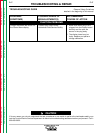
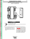
CAPACITOR DISCHARGE PROCEDURE (continued)
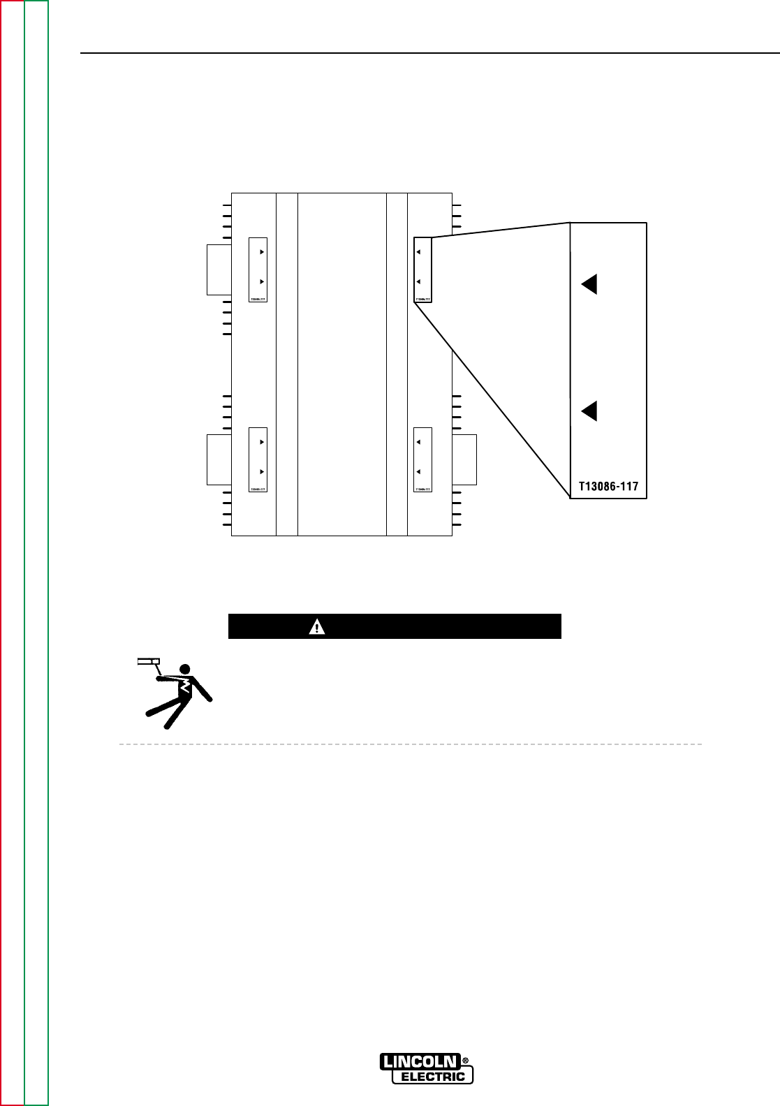
FIGURE F.3 – DISCHARGE LABEL
D
I
S
C
H
A
R
G
E
D
I
S
C
H
A
R
G
E
D
I
S
C
H
A
R
G
E
D
I
S
C
H
A
R
G
E
D
I
S
C
H
A
R
G
E
TROUBLESHOOTING & REPAIR
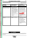
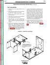
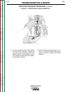
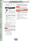
9. Using the insulated, needle nose type
jumper leads and insulated gloves, con-
nect one jumper lead to one end of the
resistor obtained in step 6. Connect the
other jumper lead to the other end of the
resistor.
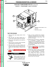
10. Carefully connect the needle nose end of
one of the jumper leads to terminal #9.
See Figure F.5. Connect the needle nose
end of the other jumper lead to terminal
#12. Terminals #9 and #12 are indicated
by the "Discharge" label. Leave the resis-
tor connected for 10 seconds. DO NOT
TOUCH TERMINALS, RESISTORS, OR
ANY INTERNAL MACHINE COMPO-
NENTS DURING THIS PROCEDURE!
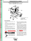
WARNING
ELECTRIC SHOCK can kill.
Proceed with caution. Be careful not to touch any internal machine components
during the discharge procedure.