


F-36 F-36
AUXILIARY TRANSFORMER PRIMARY WIRING HARNESS TEST (continued)
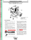
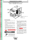
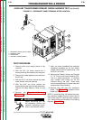
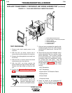
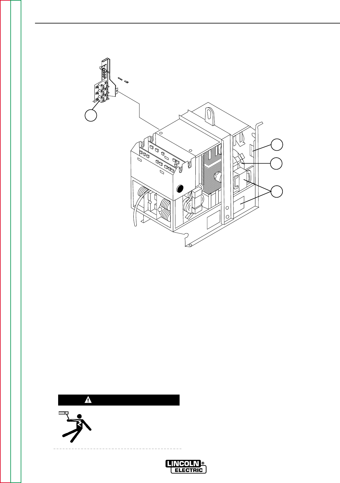
FIGURE F.9 - RECONNECT PANEL/TERMINAL STRIP LOCATION
1
3
2
4
TROUBLESHOOTING & REPAIR
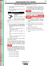
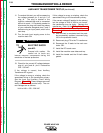
TEST PROCEDURE
1. Remove main input supply power to the
machine.
2. With the 3/8" nut driver, remove the 4
screws that hold the handle to the machine.
3. Remove the rubber gasket (cover seal) from
the lift bail.
4. With the 5/16" nut driver, remove the sheet
metal screws from the case top.
5. With the 5/16" nut driver, remove the
screws holding the right and left case sides.
Remove the case sides by lifting up and
out.
6. Perform the Capacitor Discharge
Procedure described in this section of the
manual.
Before continuing with the
test procedure, perform the
capacitor discharge proce-
dure to avoid electric shock.
7. After you have completed the capacitor
discharge procedure for all four switch
boards, remove the PC board cover. Use
the 5/16" nut driver.
8. Remove the 5 leads ( 3 heavy and 2 small)
T1, T2, T3 from main input contactor CR1.
This is a safety precaution. It prevents
high voltage from being put on the
machine during the test. Wrap tape
around the lead ends to insulate them and
prevent them from touching.
9. Remove plug J30 from the protection
board. See Figure F.1 for location of the
board and plug J30.
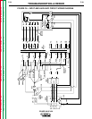
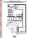
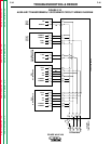
NOTE: If removing plug J30 solves the prob-
lem, check for a short circuit or a fault in the 24
VAC circuit (plug P71) and the main contactor
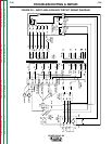
coil. See the Input and Auxiliary Circuit Wiring
Diagram, Figure F.10.
POWER WAVE 450
Return to Section TOC Return to Section TOC Return to Section TOC Return to Section TOC
Return to Master TOC Return to Master TOC Return to Master TOC Return to Master TOC
WARNING
1. RECONNECT PANEL (ON LEFT SIDE)
2. TERMINAL STRIP
3. FAN MOTORS
4. AUXILIARY TRANSFORMERS