


Return to Section TOC Return to Section TOC Return to Section TOC Return to Section TOC
Return to Master TOC Return to Master TOC Return to Master TOC Return to Master TOC
F-91 F-91
STATIC CAPACITOR BALANCE TEST (continued)
TROUBLESHOOTING & REPAIR
ELECTRIC SHOCK
can kill.
With input supply power ON,
there are high voltages
inside the machine. Do not reach into the
machine or touch any internal part of the
machine, including resistors R9 and R10. Use
insulated gloves to measure the resistance
across these resistors.
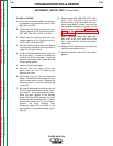
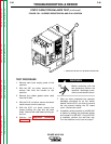
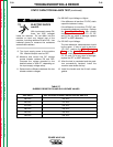
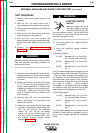
9. Turn input supply power to the machine
ON. Machine output must be OFF.
10. Measure and record the DC voltage
across bleeder resistors R9 and R10.
Compare the voltage recorded to the
desired values in Table F.7, depending on
the input supply voltage setup.
11. Determine the difference between the two
bleeder resistor voltages.
For 380 VAC Input Voltage or Higher:
If the difference is less than 75 VDC, static
capacitive balance is okay.
If the difference is more than 75 VDC, sta-
tic capacitive balance is not okay. Perform
the Input Rectifier Test. Also visually
check input filter capacitors C1, C2, C3,
and C4 for any signs of damage; replace
the FET or IGBT assembly.
For 220 VAC Input Voltage:
The two resistance measurements should
be the same. If one or both is less than
175 VDC, perform the Main Contactor
Test and the Input Rectifier Test. Also
visually check input filter capacitors C1,
C2, C3, and C4 for any signs of damage;
replace the FET or IGBT assembly.
12. After the test is completed and the prob-
lem successfully repaired, install the
machine case sides and top.
13. Install the handle and the lift bail rubber
gasket.
POWER WAVE 450
WARNING
TABLE F.7
BLEEDER RESISTOR R9 AND R10 VOLTAGE VALUES
VAC INPUT VDC ACROSS BLEEDER RESISTORS R9 AND R10
460 VAC 325 VDC
440 VAC 311 VDC
415 VAC 293 VDC
380 VAC 269 VDC
230 VAC 325 VDC
208 VAC 294 VDC