


Return to Section TOC Return to Section TOC Return to Section TOC Return to Section TOC
Return to Master TOC Return to Master TOC Return to Master TOC Return to Master TOC
POWER WAVE 450
F-37 F-37
AUXILIARY TRANSFORMER PRIMARY WIRING HARNESS TEST (continued)
TROUBLESHOOTING & REPAIR
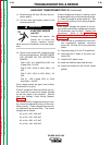
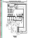
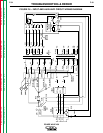
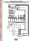
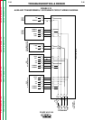
10. Check the wires that run from the recon-
nect panel to the terminal strip. Look for
shorts between wires caused by broken or
burned insulation. See the Input and
Auxiliary Circuit Wiring Diagram, Figure
F.10.
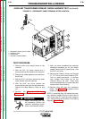
11. Check for shorts in the wires that run from
the terminal strip to the auxiliary trans-
formers and to the fan motors.
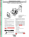
12. The fan motors or the auxiliary transformer
may be faulty. Disconnect these compo-
nents one at a time and see if fuse F1
blows when input power is applied. The
internal resistance of the fan motors
should be about 16 ohms.
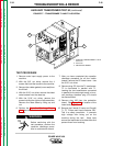
13. Remove plug P70 from the transformer. If
this solves the problem, check for a short
in the secondary circuit. See the machine
Wiring Diagram and the Protection PC
Board Schematic in the Electrical
Diagrams section of this manual.
14. After the test is completed and the prob-
lem successfully repaired, reconnect plug
J30 to the protection board.
15. Reconnect plugs P70 and P71 to the T1
transformer.
16. Reconnect the 5 leads to the main con-
tactor CR1.
17. Install the PC board cover.
18. Install the machine case sides and top.
19. Install the handle and the lift bail rubber
gasket.