


F-94 F-94
DYNAMIC CAPACITOR BALANCE TEST (continued)
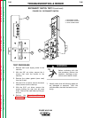
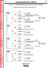
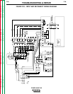
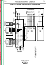
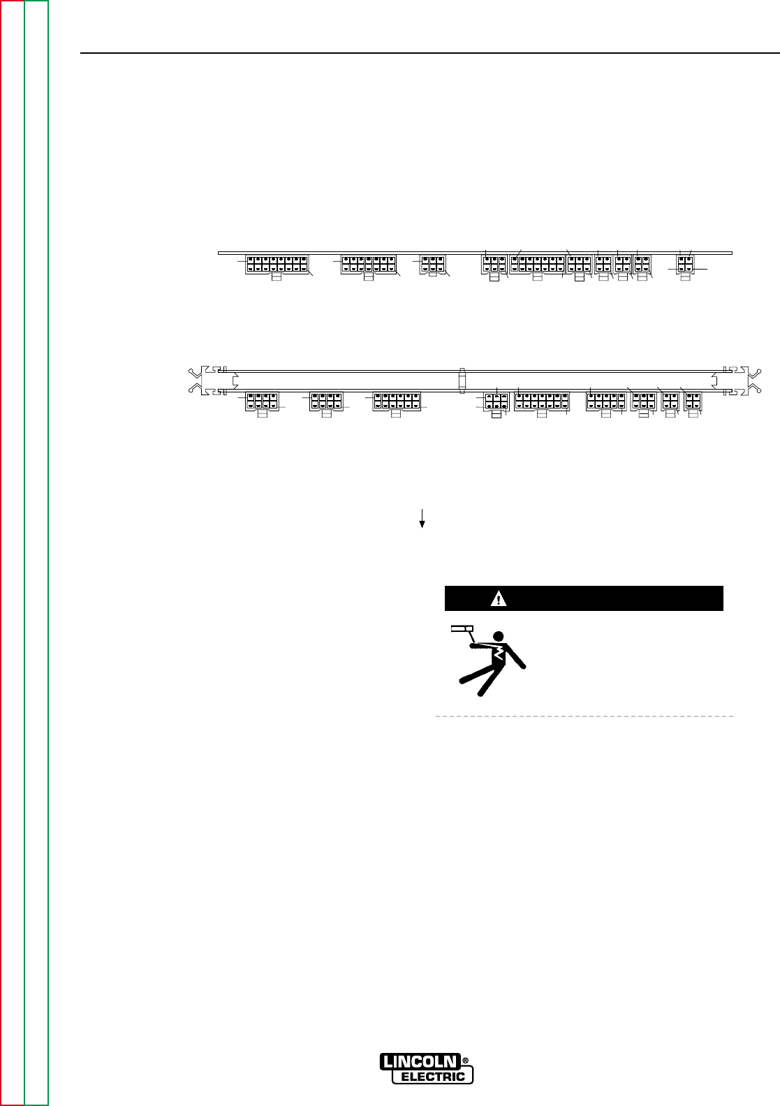
FIGURE F.32- CONTROL BOARD PLUG LOCATIONS
PROTECTION BD
GROUND PLANE
CONTROL BD
J20 J21 J22 J23 J24 J25 J26 J27 J28
J30 J31 J32 J33 J34 J35
J36
J37
J38
J39
1
16
1
14
1
6
1
6
1
14
1
6
1 1 1
1
4
4
4
4
1
8
1
8
1
12
6
1
1
14
1
10
1
6
1
4
1
4
DISPLAY
2
3
4
2
TROUBLESHOOTING & REPAIR
TEST PROCEDURE
1. Remove main input supply power to the
machine.
2. With the 3/8" nut driver, remove the 4
screws that hold the handle to the machine.
3. Remove the rubber gasket (cover seal) from
the lift bail.
4. With the 5/16" nut driver, remove the sheet
metal screws from the case top.
5. With the 5/16" nut driver, remove the
screws holding the right and left case sides.
Remove the case sides by lifting up and
out.
6. Perform the Capacitor Discharge Proce-
dure described earlier in this section of the
manual.
Before continuing with the
test procedure, perform the
capacitor discharge proce-
dure to avoid electric shock.
7. After you have completed the capacitor dis-
charge procedure for all four switch boards,
use the 5/16" nut driver to remove the two
screws that hold the PC board cover.
Remove the cover.
8. Connect the machine negative (-) output
terminal to earth ground. Connect the
oscilloscope case ground to earth ground.
9. Connect the oscilloscope to plug J23 - pin
4 (positive side) and plug J23 - pin 2 (nega-
tive side) on the control board. See Figure
F.32 for location If these connections are
reversed, you will not be able to see the fre-
quency train on the oscilloscope. Set the
oscilloscope to be DC coupled with 2
volts/division and 0.2 milliseconds/division.
POWER WAVE 450
Return to Section TOC Return to Section TOC Return to Section TOC Return to Section TOC
Return to Master TOC Return to Master TOC Return to Master TOC Return to Master TOC
WARNING
TOP VIEW