


PREVENTIVE MAINTENANCE
Perform the following preventive maintenance proce-
dures at least once every six months. It is good prac-
tice to keep a preventive maintenance record; a record
tag attached to the machine works best.
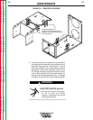
1. Remove the hex head screws from the sides and
top of the machine. Remove the handle bar and
the machine wrap-around cover. Remove the two
case sides. There are hex head screws on each
side.
2. Perform the input filter capacitor discharge proce-
dure described at the beginning of the
Maintenance Section.
3. Disconnect the shunt from the negative (-) output
terminal. Failure to do this could cause damage to
the shunt circuitry.
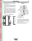
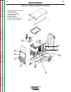
4. Clean the inside of the machine with a low pres-
sure airstream. Be sure to clean the following
components thoroughly (Refer to Figure D.4):
• Display, Snubber, and Shunt printed circuit
boards
• Power Switch
• Main Transformer
• Auxiliary Transformers
• Input Rectifier
• Heat Sink Fins
• Input Filter Capacitors
• Output Terminals
• Terminal Strip
5. Examine the capacitors for leakage or oozing.
Replace if needed.
6. Examine the wrap-around and side covers for
dents and breakage. Repair them as needed. The
covers must be kept in good condition to assure
that high voltage parts are protected and that cor-
rect spacings are maintained.
7. Remove welding cables and check the electrical
ground continuity. Use an ohmmeter to measure
the resistance between each output terminal and
an unpainted surface of the machine case. The
meter reading should be 500,000 ohms or more. If
the meter reading is less than 500,000 ohms,
check for electrical components that are not prop-
erly insulated from the case. Correct component
insulation, if needed.
8. Reconnect the shunt and wire #467 to the nega-
tive (-) output terminal. Make sure the connection
is tight.
9. Replace and secure the machine covers and han-
dle bar.
10. Remove the overlay from the front panel of the
machine. Clean the plastic case with a low pres-
sure airstream. Wipe the sensors (Fig D.4 Item 8)
with a clean, soft cloth. Make sure the sensors are
not scratched in the process.
11. Check the back of the overlays. If the bar code
(black square(s)) on the back of the overlay is
scratched, apply a dull black spray finish to the
scratched-off areas only. If a large area of the bar
code is scratched off, the machine either will not
recognize the overlay or will mistake the overlay
for another one.
12. Inspect gun and cables for good condition.
MAINTENANCE
D-5 D-5
POWER WAVE 450
Return to Section TOC Return to Section TOC Return to Section TOC Return to Section TOC
Return to Master TOC Return to Master TOC Return to Master TOC Return to Master TOC