


TROUBLESHOOTING & REPAIR
F-208 F-208
POWER WAVE 450
Return to Section TOC Return to Section TOC Return to Section TOC Return to Section TOC
Return to Master TOC Return to Master TOC Return to Master TOC Return to Master TOC
PRE-POWERUP SWITCH BOARD TEST PROCEDURE
FOR REPLACEMENT OF SWITCH ASSEMBLY G2402-2 (continued)
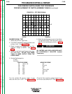
5. Press the MANUAL PROCEDURE ENTRY
Key on the Calibration and Test Overlay and
change the Power Wave to “Process 1 Setup 1
-8” mode.
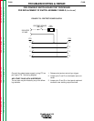
6. Turn the arc start switch ON. See Arc Start
PW450 or Figure F.79.
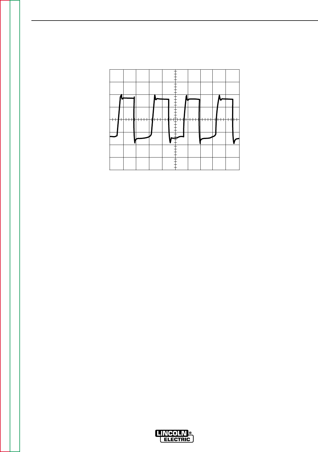
7. Adjust the output grid load to get 400 amps at
36VDC. The oscilloscope picture should look
like Figure F.84.
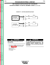
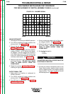
*ALTERNATE TEST (without current probe)
1. Connect a transformer isolated oscilloscope
as follows:
Set oscilloscope for .2v/div and 10us/div
Probe J21 pin 1 wire #211
Common J21 pin 5 wire #215
2. Observe a waveform similar to Figure F.84.
Equal amplitude and symmetry of the pulses is
important.
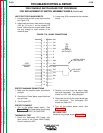
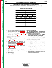
3. Check the capacitor voltages. The capacitor
voltages must be within eight volts of each
other.
4. Turn the arc start switch OFF. See Arc Start
PW450 or Figure F.79
5. Turn OFF the Power Wave and remove the
input power. Make sure the filter capacitors are
completely discharged. See Figure F.77.
PREPARE MACHINE FOR NORMAL
OPERATION.
1. Turn the power switch OFF and remove input
power to the machine.
2. The input capacitors must be discharged
before continuing.
3. Remove the capacitor voltage monitoring
leads. See Figure F.77.
4. Remove the power input cable from CR1.
5. Remove the output cables from the Power
Wave.
6. Remove the arc start switch circuit.
7. Enable the water cooler if it was enabled at the
start of this test.
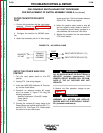
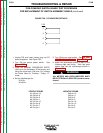
FIGURE F.84 - PRIMARY CURRENT SIGNAL
0 V
10V/Div
10uS/Div