


Return to Section TOC Return to Section TOC Return to Section TOC Return to Section TOC
Return to Master TOC Return to Master TOC Return to Master TOC Return to Master TOC
F-54 F-54
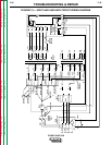
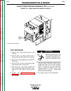
OUTPUT SHUNT/WELDING FEEDBACK TEST (continued)
TROUBLESHOOTING & REPAIR
ELECTRIC SHOCK
can kill.
Proceed with caution. Be
careful not to touch any inter-
nal machine components during the remainder
of the test procedure.
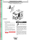
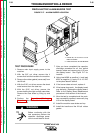
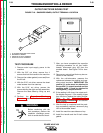
9. Check for +15 VDC between plug J50 -
pin 3+ and J50 - pin 1-.
10. Carefully move the probes, placing the
negative probe (-) at plug J50 - pin 6 and
the positive (+) probe at J50 - pin 1.
Check for -15 VDC.
11. If the voltage readings are NOT correct,
check the associated wiring to the control
board. If the wiring is okay, the control
board may be faulty. Replace the control
board. Refer to the Printed Circuit Board
Removal and Replacement Procedure
in this section of the manual.
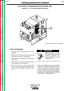
12. If the supply voltage readings are correct,
load the machine to 400 amps.
Do not run the machine under load for more
than 15 sec. with case removed.
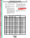
13. Use a current probe to check for 5 ma of
current through lead #218 (plug J50 - pin
4). This also reads approximately 1 VDC if
you use a voltmeter.
14. If the current reading is NOT correct, the
shunt amplifier board may be faulty.
Replace the shunt amplifier assembly and
perform current calibration.
15. If the current reading IS correct, the con-
trol board may be faulty. Replace the con-
trol board. Refer to the Printed Circuit
Board Removal and Replacement proce-
dure in this section of the manual.
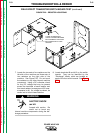
16. After the test is completed and the prob-
lem successfully repaired, install the
machine case sides and top.
17. Install the handle and the lift bail rubber
gasket.
WARNING
CAUTION