


F-61 F-61
FIELD EFFECT TRANSISTOR/SWITCH BOARD TEST (continued)
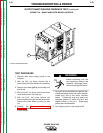
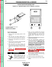
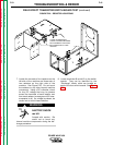
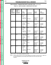
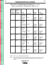
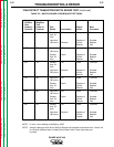
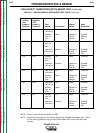
FIGURE F.20 - RESISTOR LOCATIONS
TROUBLESHOOTING & REPAIR
7. Locate the two sets of two resistors on the
left side of the machine and three sets of
two resistors on the right side of the
machine. See Figure F.20. Do not touch
the resistors or any other internal machine
component. Using a DC voltmeter, check
for any DC voltage that may be present
across the terminals of each resistor and
from each resistor to case ground (20 mea-
surements in all). If a voltage is present, be
careful not to touch these resistors.
ELECTRIC SHOCK
can kill.
Proceed with caution. Be
careful not to touch any
internal machine components during the dis-
charge procedure.
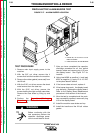
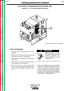
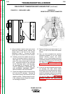
8. Locate terminals #9 and #12 on the switch
boards. They can be identified by the
“Discharge” labels, which are located on
each of the four switch boards. See Figure
F.21.
POWER WAVE 450
Return to Section TOC Return to Section TOC Return to Section TOC Return to Section TOC
Return to Master TOC Return to Master TOC Return to Master TOC Return to Master TOC
WARNING
5 PAIRS OF RESISTORS
CHECK VOLTAGES BETWEEN
EACH TERMINAL AND FROM
EACH RESISTOR TO CASE
GROUND