


F-48 F-48
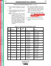
INPUT RECTIFIER RESISTANCE TEST (continued)
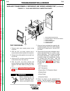
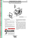
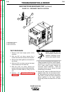
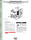
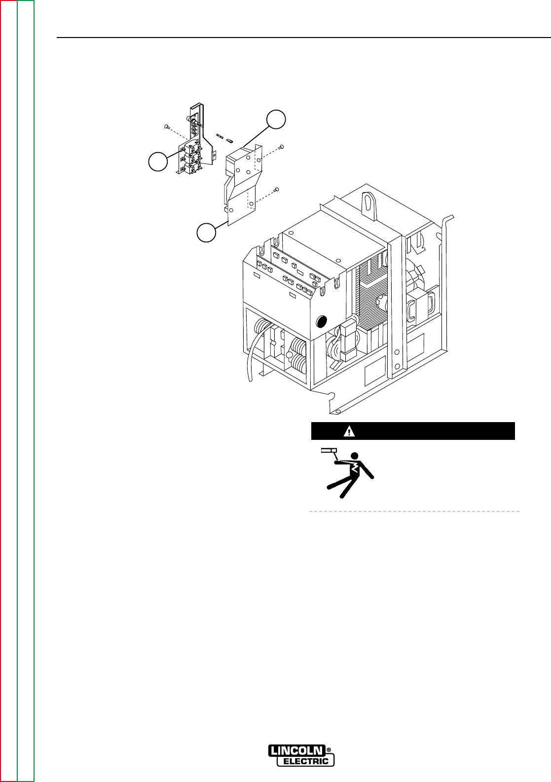
FIGURE F.15 - RECONNECT SWITCH LOCATION
1
2
3
TROUBLESHOOTING & REPAIR
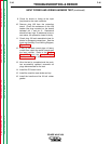
TEST PROCEDURE
1. Remove main input supply power to the
machine.
2. With the 3/8" nut driver, remove the 4
screws that hold the handle to the machine.
3. Remove the rubber gasket (cover seal) from
the lift bail.
4. With the 5/16" nut driver, remove the sheet
metal screws from the case top.
5. With the 5/16" nut driver, remove the
screws holding the right and left case sides.
Remove the case sides by lifting up and
out.
6. Perform the Capacitor Discharge
Procedure described earlier in this section
of the manual.
Before continuing with the
test procedure, perform the
capacitor discharge proce-
dure to avoid electric shock.
7. After you have completed the capacitor dis-
charge procedure for all four switch boards,
use the 5/16" nut driver to remove the two
5/16" sheet metal screws holding the
reconnect switch assembly. Twist the
reconnect switch out to access the lead
connections on the back.
8. Use the 3/8" wrench to disconnect the two
negative leads from the reconnect switch.
By disconnecting the leads at the recon-
nect switch, you will not have to disturb the
silicon applied to the input rectifier.
Electrically isolate the leads from all other
leads.
POWER WAVE 450
Return to Section TOC Return to Section TOC Return to Section TOC Return to Section TOC
Return to Master TOC Return to Master TOC Return to Master TOC Return to Master TOC
WARNING
1. RECONNECT SWITCH
2. INPUT RECTIFIER
3. MAIN CONTACTOR