


Return to Section TOC Return to Section TOC Return to Section TOC Return to Section TOC
Return to Master TOC Return to Master TOC Return to Master TOC Return to Master TOC
F-153 F-153
CURRENT CALIBRATION (continued)
TROUBLESHOOTING & REPAIR
PROCEDURE
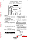
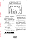
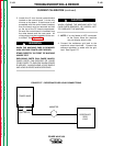
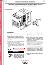
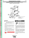
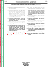
1. Install the Test and Calibration Overlay and
apply power to the machine. See Figure
F.58.
2. Press the Manual Procedure Entry Key (64).
The machine should display the following:
PROCESS 1 SETUP
1-0
3. Toggle the Arrow Keys (100 and 101) until
the display reads:
PROCESS 1 SETUP
1-6
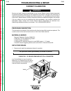
4. Activate the external trigger device.
(K941-1) and load the machine.
The machine’s output terminals will be electri-
cally “HOT” when the trigger circuit is
activated.
5. Adjust the potentiometer until the reference
(external ammeter) reads 304 amps +/- 1.0
amps. The load voltage should be greater
than 15 volts but less than 35 volts.
6. Remove power to the machine.
7. If necessary re-install the control board.
8. Replace the machine case parts.
POWER WAVE 450
WARNING
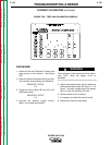
FIGURE F.58 – TEST AND CALIBRATION OVERLAY