


TROUBLESHOOTING & REPAIR
F-204 F-204
POWER WAVE 450
Return to Section TOC Return to Section TOC Return to Section TOC Return to Section TOC
Return to Master TOC Return to Master TOC Return to Master TOC Return to Master TOC
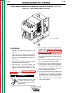
PRE-POWERUP SWITCH BOARD TEST PROCEDURE
FOR REPLACEMENT OF SWITCH ASSEMBLY G2402-2 (continued)
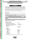
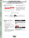
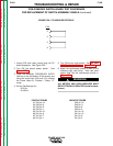
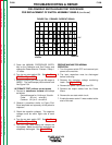
1. Unplug P23 and insert jumper plug into PC
board receptacle. See Figure F.80.
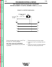
2. Turn ON the preset power switch. See
Figure F.78.
3. Press the MANUAL PROCEDURE ENTRY
(64) key on the Calibration & Test overlay and
using the arrow keys (100) and (101) change
the Power Wave to “Process 1 Setup 1-1”
mode.
4. Set the Oscilloscope for:
20 V/div.
20 uS/div.
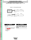
5. Turn ON the arc start switch. See Arc Start
PW450 with wire Feeder or Figure F.79.
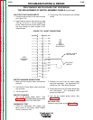
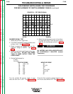
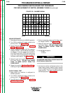
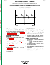
6. Attach the oscilloscope probes to each of the
following eight test points. Each test point
should look like the oscilloscope picture in
Figure F.81.
ALL METERS AND OSCILLOSCOPES MUST
BE ELECTRICALLY ISOLATED (isolation trans-
former).
FIGURE F.80 - PC BOARD RECEPTACLE
2
3
5
6
P 23
WARNING
POSITIVE PROBE
#1 P40 pin 14
#2 P40 pin 9
#3 P40 pin 6
#4 P40 pin 1
#5 P41 pin 15
#6 P41 pin 9
#7 P41 pin 7
#8 P41 pin 1
NEGATIVE PROBE
P40 pin 16
P40 pin 11
P40 pin 8
P40 pin 3
P41 pin 16
P41 pin 10
P41 pin 8
P41 pin 2