


F-90 F-90
STATIC CAPACITOR BALANCE TEST (continued)
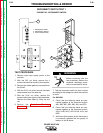
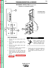
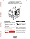
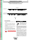
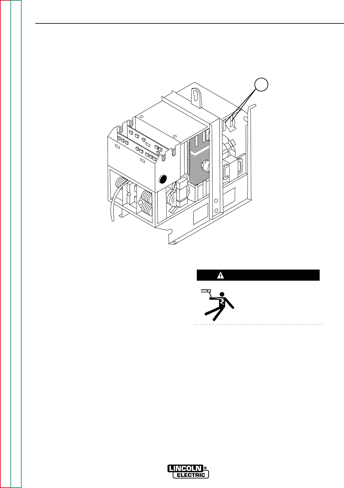
FIGURE F.30 - BLEEDER RESISTORS R9 AND R10 LOCATION
1
TROUBLESHOOTING & REPAIR
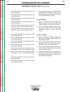
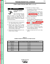
TEST PROCEDURE
1. Remove main input supply power to the
machine.
2. With the 3/8" nut driver, remove the 4
screws that hold the handle to the
machine.
3. Remove the rubber gasket (cover seal)
from the lift bail.
4. With the 5/16" nut driver, remove the sheet
metal screws from the case top.
5. With the 5/16" nut driver, remove the
screws holding the right and left case
sides. Remove the case sides by lifting up
and out.
6. Perform the Capacitor Discharge
Procedure described earlier in this section
of the manual.
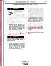
Before continuing with the
test procedure, perform the
capacitor discharge proce-
dure to avoid electric shock.
7. After you have completed the capacitor
discharge procedure for all four switch
boards, use the 5/16" nut driver to remove
the two screws holding the PC board
cover. Remove the cover.
8. If possible, set the machine up for 380 VAC
or above by setting the reconnect switch
and Jumper A to 380 VAC. If only 220 VAC
is available, perform the test that way.
Turn the machine on but have no output.
POWER WAVE 450
Return to Section TOC Return to Section TOC Return to Section TOC Return to Section TOC
Return to Master TOC Return to Master TOC Return to Master TOC Return to Master TOC
WARNING
1. RESISTORS R9 AND R10 (BLEEDER RESISTORS)