


Return to Section TOC Return to Section TOC Return to Section TOC Return to Section TOC
Return to Master TOC Return to Master TOC Return to Master TOC Return to Master TOC
F-152 F-152
CURRENT CALIBRATION (continued)
TROUBLESHOOTING & REPAIR
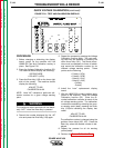
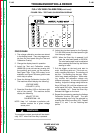
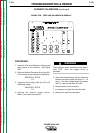
2. Locate the 10 turn trimmer potentiometer
located on the control board. It is the only
trimmer on the board. If the trimmer is not
accessible with the control board installed,
then the board must be removed and laid
on the top of the PC board compartment.
Be sure the control board is insulated from
the other boards and the case parts. All
wiring plugs must be connected to the con-
trol board. See Figure F.56.
WHEN THE MACHINE CASE IS REMOVED
HIGH VOLTAGE POINTS ARE EXPOSED.
STAND DIRECTLY IN FRONT OF MACHINE
UNDER TEST.
EXPLODING PARTS CAN CAUSE INJURY.
FAILED PARTS CAN EXPLODE OR CAUSE
OTHER PARTS TO EXPLODE WHEN POWER
IS APPLIED. ALWAYS WEAR A FACE SHIELD
AND LONG SLEEVES WHEN SERVICING.
WHEN LOADING THE MACHINE WITH THE
CASE PARTS REMOVED. BE CAREFUL NOT
TO OVER HEAT THE MACHINE.
3. NOTE: If a wire feeder is NOT connected
to the Power Wave the machine
may not display output volts.
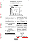
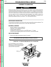
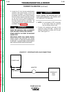
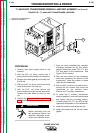
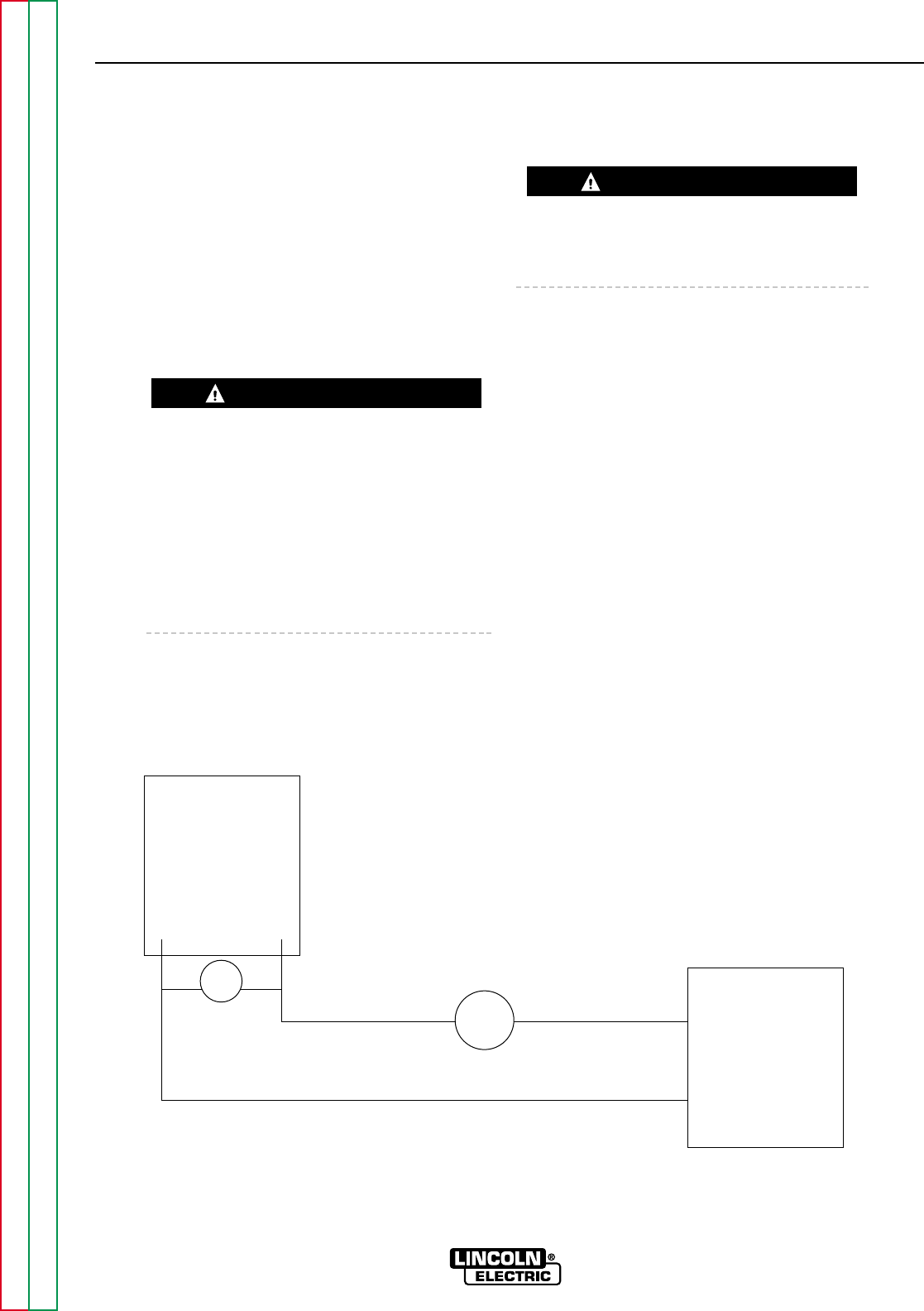
4. Connect the resistance grid load to the
machine’s output terminals. Connect the
reference ammeter in series with the grid
load. See Figure F.57.
POWER WAVE 450
WARNING
FIGURE F.57 – RESISTANCE GRID LOAD CONNECTIONS
CAUTION
POWER WAVE
RESISTANCE
GRID
LOAD
AMMETER
VOLT METER
+
–