


Return to Section TOC Return to Section TOC Return to Section TOC Return to Section TOC
Return to Master TOC Return to Master TOC Return to Master TOC Return to Master TOC
POWER WAVE 450
F-64 F-64
FIELD EFFECT TRANSISTOR/SWITCH BOARD TEST (continued)
TROUBLESHOOTING & REPAIR
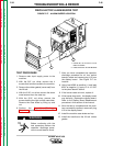
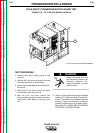
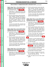
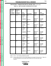
Switch Board Test 1: (For Switch Board
Marked CAP 1 on the Switch Board Assem-
bly Connection Decal - See Figure F.23.)
A. Disconnect all wiring harness leads from
switch board 1. Fold the leads up so that
they do not interfere with the exposed PC
board terminals.
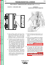
B. With the volt/ohmmeter, measure the resis-
tance between terminals according to
Table F. 2. See Figure F.23 for the locations
of the terminals. If any test fails, replace all
four switch boards. Refer to the FET
Module Assembly Removal and Re-
placement procedure in this section of the
manual.
If none of the tests fails, reconnect the
wiring harness leads to switch board 1 and
perform switch board test 2.
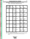
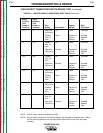
Switch Board Test 2: (For Switch Board
Marked CAP 2 on the Switch Board Assem-
bly Connection Decal - See Figure F.23.)
A. Disconnect all wiring harness leads from
switch board 2. Fold the leads up so that
they do not interfere with the exposed PC
board terminals.
B. With the volt/ohmmeter, measure the resis-
tance between terminals according to
Table F. 3. If any test fails, replace all four
switch boards. Refer to the FET Module
Assembly Removal and Replacement pro-
cedure in this section of the manual.
If none of the tests fails, reconnect the
wiring harness leads to switch board 2 and
perform switch board test 3.
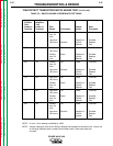
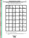
Switch Board Test 3: (For Switch Board
Marked CAP 3 on the Switch Board Assem-
bly Connection Decal - See Figure F.23.)
A. Disconnect all wiring harness leads from
switch board 3. Fold the leads up so that
they do not interfere with the exposed PC
board terminals.
B. With the volt/ohmmeter, measure the resis-
tance between terminals according to
Table F. 4. If any test fails, replace all four
switch boards. Refer to the FET Module
Assembly Removal and Replacement pro-
cedure in this section of the manual.
If none of the tests fails, reconnect the
wiring harness leads to switch board 3 and
perform switch board test 4.
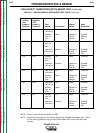
Switch Board Test 4: (For Switch Board
Marked CAP 4 on the Switch Board Assem-
bly Connection Decal - See Figure F.23.)
A. Disconnect all wiring harness leads from
switch board 4. Fold the leads up so that
they do not interfere with the exposed PC
board terminals.
B. With the volt/ohmmeter, measure the resis-
tance between terminals according to
Table F. 5. If any test fails, replace all four
switch boards. Refer to the FET Module
Assembly Removal and Replacement pro-
cedure in this section of the manual.
If none of the tests fails, reconnect the
wiring harness leads to switch board 4.
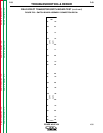
IGBT Switch Board Test (G3165-1) See Table
F.6.
A. Disconnect all wiring harness leads from
the switch boards. Fold the leads up so
that they do not interfere with the exposed
PC board terminals.
B. With the Volt/Ohmmeter, measure the
resistance between terminals according to
Table F.6. If any test fails, replace all four
switch boards. Refer to the FET Module
Assembly Removal and Replacement pro-
cedure in this section of the manual.
If none of the tests fail, reconnect the wiring
harness leads to the switch boards.
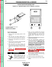
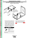
15. After the test is completed and the prob-
lem successfully repaired, install the
machine case sides and top.
16. Install the handle and the lift bail rubber
gasket.