


Return to Section TOC Return to Section TOC Return to Section TOC Return to Section TOC
Return to Master TOC Return to Master TOC Return to Master TOC Return to Master TOC
F-77 F-77
SNUBBER AND BLEEDER RESISTOR TEST (continued)
TROUBLESHOOTING & REPAIR
TEST PROCEDURE
1. Remove main input supply power to the
machine.
2. With the 3/8" nut driver, remove the 4
screws that hold the handle to the machine.
3. Remove the rubber gasket (cover seal) from
the lift bail.
4. With the 5/16" nut driver, remove the sheet
metal screws from the case top.
5. With the 5/16" nut driver, remove the
screws holding the right and left case sides.
Remove the case sides by lifting up and
out.
6. Perform the Capacitor Discharge Proce-
dure described earlier in this section of the
manual.
Before continuing with the
test procedure, perform the
capacitor discharge proce-
dure to avoid electric shock.
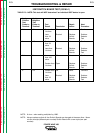
7. Perform the following tests on the four
switch boards:
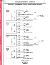
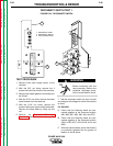
Switch Board 1: (Switch Board 1 is Marked
CAP 1 on the Switch Board Assembly
Connection Decal - See Figure F.24.)
A. Remove quick connect terminals #401,
#402, #9, and #12 from switch board 1.
B. With the volt/ohmmeter, check for 25
ohms resistance between lead #401 and
#12E.
If the measurement reads between 20 and
30 ohms, resistor R1 and leads #401 and
#12E are okay. Go to step C.
If the measurement does not read between
20 and 30 ohms, check for continuity in
leads #401 and #12E. Then test for 25
ohms resistance across R1 directly. If the
measurement does not read between 20
and 30 ohms, replace resistor R1.
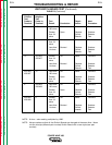
C. With the volt/ohmmeter, check for 25
ohms resistance between lead #402 and
#9E.
If the measurement reads between 20 and
30 ohms, resistor R2 and leads #402 and
#9E are okay. Go to step D.
If the measurement does not read between
20 and 30 ohms, check for continuity in
leads #402 and #9E. Then test for 25
ohms resistance across R2 directly. If the
measurement does not read between 20
and 30 ohms, replace resistor R2.
D. With the volt/ohmmeter, check for 7.5 K-
ohms resistance between lead #12L (12E)
and #9L (9E).
If the measurement reads between 6.75
and 8.25 K-ohms, resistor R9 and leads
#12L(12E) and #9L (9E) are okay. Go to
step E.
If the measurement does not read between
6.75 and 30 K-ohms, check for continuity
in leads #12L (12E) and #9L(9E). Then test
for 7.5 K-ohms resistance across R9
directly. If the measurement does not read
between 6.75 and 8.25 K-ohms, replace
resistor R9.
E. Reconnect quick connect terminals #401,
#402, #9, and #12 on switch board 1.
Switch Board 2: (Switch Board 2 is Marked
CAP 2 on the Switch Board Assembly
Connection Decal - See Figure F.24.)
A. Remove quick connect terminals #403,
#404, #9, and #12.
B. With the volt/ohmmeter, check for 25
ohms resistance between lead #403 and
#12F.
If the measurement reads between 20 and
30 ohms, resistor R3 and leads #403 and
#12F are okay. Go to step C.
If the measurement does not read between
20 and 30 ohms, check for continuity in
leads #403 and #12F. Then test for 25
ohms resistance across R3 directly. If the
measurement does not read between 20
and 30 ohms, replace resistor R3.
POWER WAVE 450
WARNING