


F-158 F-158
WATER COOLER REMOVAL AND REPLACEMENT (continued)
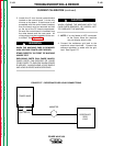
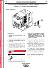
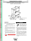
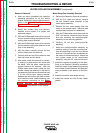
FIGURE F.60 - WATER COOLER LOCATION
1
3
2
TROUBLESHOOTING & REPAIR
PROCEDURE
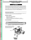
NOTE: These instructions may vary slightly
with later model coolers. See instruc-
tions included with cooler kit.
1. Remove main input supply power to the
machine.
2. With the 3/8" nut driver, remove the 4
screws that hold the handle to the machine.
3. Remove the rubber gasket (cover seal) from
the lift bail.
4. With the 5/16" nut driver, remove the sheet
metal screws from the case top.
5. With the 5/16" nut driver, remove the
screws holding the right and left case sides.
Remove the case sides by lifting up and
out.
6. Perform the Capacitor Discharge Proce-
dure described earlier in this section of the
manual.
Before continuing with the
test procedure, perform the
capacitor discharge proce-
dure to avoid electric shock.
7. After you have completed the capacitor dis-
charge procedure for all four switch boards,
use the 5/16" nut driver to remove the water
cooler access door. See Figure F.60 for
location.
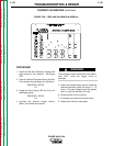
8. With the 3/8" open end or socket wrench,
remove the two water cooler assembly
mounting screws. Slide the assembly to
the left to better access the circuit breaker,
which will be removed in a moment.
9. With the 5/16" nut driver, remove the two
sheet metal screws holding the lower case
back panel.
POWER WAVE 450
Return to Section TOC Return to Section TOC Return to Section TOC Return to Section TOC
Return to Master TOC Return to Master TOC Return to Master TOC Return to Master TOC
WARNING
1. WATER COOLER ACCESS DOOR (ON
BACK PANEL)
2. WATER COOLING FITTINGS
3. CIRCUIT BREAKER