


TROUBLESHOOTING & REPAIR
F-206 F-206
POWER WAVE 450
Return to Section TOC Return to Section TOC Return to Section TOC Return to Section TOC
Return to Master TOC Return to Master TOC Return to Master TOC Return to Master TOC
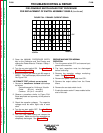
PRE-POWERUP SWITCH BOARD TEST PROCEDURE
FOR REPLACEMENT OF SWITCH ASSEMBLY G2402-2 (continued)
460VAC RECONNECT
1. Reconfigure the machine for 460VAC operation.
2. Turn ON the variable AC supply applied to the
primary circuit. See Figure F.76.
3. Turn on the arc start switch. See Arc Start
PW450 or Figure F.79.
4. Slowly increase the voltage until filter capacitor
voltage is 25VDC. NOTE: Monitor both capaci-
tor voltages. If the two voltages are not within 5
to 8 VDC of each other STOP and check wiring
to the FET switch board assembly and also the
individual switch boards. See Figure F.77.
5. Adjust the grid load to get 5 amps output from
the Power Source. DO NOT PULL MORE
THAN 7-8 AMPS OUTPUT FROM THE
POWER WAVE.
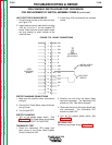
6. Repeat the previous Snubber Signal Test by
checking the eight test points.
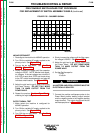
OUTPUT SIGNAL TEST
1. Make certain the machine is configured for
460VAC operation.
2. Turn ON the variable AC supply applied to the
primary circuit. See Figure F.76.
3. Turn ON the arc start switch. See Arc Start
PW450 or Figure F.79.
4. Slowly increase the voltage until the filter capac-
itor voltage is 25VDC. See Figure F.77.
5. Adjust the grid load to get 5 amps output from
the Power Wave. DO NOT DRAW MORE
THAN 7-8 AMPS OUTPUT FROM THE
POWER WAVE.
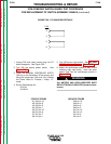
6. Set the Oscilloscope for:
5 V/div.
10 uS/div.
ALL METERS AND OSCILLOSCOPES MUST BE
ELECTRICALLY ISOLATED.
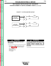
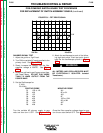
7. Connect the positive oscilloscope probe to the
Power Wave positive welding output terminal
and the negative probe to the negative welding
output terminal. The output should look like the
oscilloscope picture in Figure F.83.
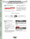
WARNING
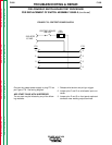
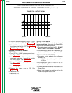
FIGURE F.82 - SNUBBER SIGNAL
0 V
5V/Div
20uS/Div