


F-125 F-125
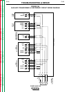
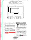
INTERNAL REMOTE CONTROL TEST (continued)
TROUBLESHOOTING & REPAIR
ELECTRIC SHOCK
can kill.
With input power ON, there
are high voltages inside the
machine, including the pro-
tection board. Do not reach
into the machine or touch any internal part.
10. Turn input power ON.
11. Turn the knob on the Remote Control Kit
all the way counterclockwise.
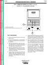
12. With the volt/ohmmeter, check the voltage
between plug J10 - pin 6 (positive) and
J10 - pin 7 (negative) on the display board.
It should be about zero volts.
13. With the Power Wave set in the SMAW
(CC) mode of operation, turn the knob on
the Remote Control Kit clockwise. The
voltage between plug J10 - pin 6 and J10
- pin 7 should increase smoothly to about
10.25 volts. If this happens but the dis-
play shows no change in the preset cur-
rent value (SET = ), replace the display
board. If the voltage between pins 6 and 7
does not increase smoothly, test the asso-
ciated wiring as follows:
A. Turn power switch SW1 to the OFF posi-
tion and disconnect input power to the
machine.
B. Perform the Capacitor Discharge Proce-
dure described earlier in this section of the
manual.
Before continuing with the test procedure, per-
form the capacitor discharge procedure to
avoid electric shock.
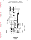
C. Remove plug J10 from the display board.
Check for continuity between the following
pins:
J10 - pin 10 and P1 - pin A (of the remote
amphenol)
J10 - pin 6 and P1 - pin B (of the remote
amphenol)
J10 - pin 7 and P1 - pin C (of the remote
amphenol)
14. If you find no continuity between any of
these pins, do the following:
A. No continuity between J10 - pin 10 and P1
- pin A (of the remote amphenol):
• Check lead #177A between the remote
amphenol and the square wave TIG pro-
tection board for continuity.
• Check lead #294 between the square
wave TIG protection board and the dis-
play board for continuity.
• Check plugs J10, J92, and J93 to make
sure the pins are seated properly and not
opened up or loose.
• Replace the square wave TIG protection
board.
B. No continuity between J10 - pin 6 and P1
- pin B (of the remote amphenol)
• Check lead #176A between the remote
amphenol and the square wave TIG pro-
tection board for continuity.
• Check lead #291 between the square
wave TIG protection board and the dis-
play board for continuity.
• Check plugs J10, J92, and J93 to make
sure the pins are seated properly and not
opened up or loose.
• Replace the square wave TIG protection
board.
C. No continuity between J10 - pin 7 and P1
- pin C (of the remote amphenol)
• Check lead #175A between the remote
amphenol and the square wave TIG pro-
tection board for continuity.
• Check lead #292 between the square
wave TIG protection board and the dis-
play board for continuity.
• Check plugs J10, J92, and J93 to make
sure the pins are seated properly and not
opened up or loose.
• Replace the square wave TIG protection
board.
15. Connect all the plugs disconnected for the
tests above.
16. Connect plug J30 into the protection
board and replace the PC board cover
with two sheet metal screws.
17. Connect the five leads to the main con-
tactor.
18. Install the machine case sides and top.
19. Install the handle and the lift bail rubber
gasket.
POWER WAVE 450
Return to Section TOC Return to Section TOC Return to Section TOC Return to Section TOC
Return to Master TOC Return to Master TOC Return to Master TOC Return to Master TOC
WARNING
WARNING